
Quick Facts
- Manufacturer: Bezares
- Product Series: BEZA
- Product Type: Lightweight fixed-displacement hydraulic gear pump
- Pump Construction: High-strength aluminum center housing with cast-iron front and rear covers
- Displacement Range: 6, 8, 10, 12, 14, or 16 cubic centimeters per revolution
- Maximum Pressure: Up to 260 bar on 6 through 14 cc models and up to 240 bar on the 16 cc model
- Maximum Speed: Up to 3,000 rpm
- Rotation Options: Clockwise or counterclockwise
- Primary Applications: Compact mobile hydraulic systems, commercial vehicles, industrial vehicles, and auxiliary equipment
- Primary Benefit: Compact hydraulic power with lower component weight
- Production Status: Current Bezares product family; confirm the required configuration and availability before ordering
Overview
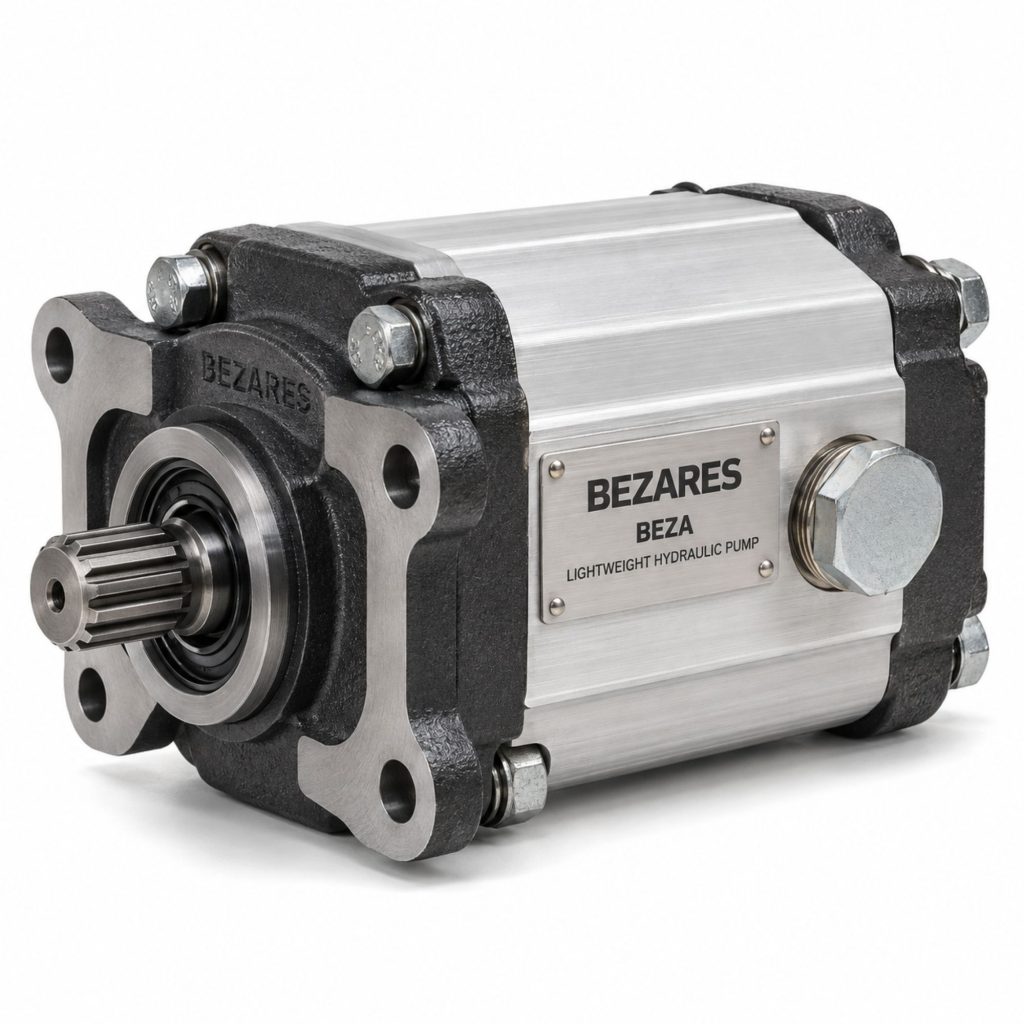
The Bezares BEZA Lightweight Hydraulic Pump is a compact external gear pump designed for mobile and industrial hydraulic applications where space, weight, pressure capability, and operating efficiency are important.
The BEZA series uses a high-strength aluminum pump body to reduce weight. Cast-iron front and rear covers reinforce the assembly at its mounting and structural load points. The pump also uses automatic axial-clearance compensation to help preserve hydraulic efficiency as pressure and operating conditions change.
Bezares offers the BEZA in six displacement sizes ranging from 6 to 16 cubic centimeters per revolution. Clockwise and counterclockwise configurations are available, allowing the pump to be matched to different PTOs, engines, electric motors, and mechanical drive arrangements.
The BEZA is a fixed-displacement pump. Its output flow is directly related to displacement and operating speed, while the pressure it develops depends on resistance from the connected hydraulic load.
Key Characteristics
- Compact fixed-displacement gear-pump design
- High-strength aluminum center housing
- Cast-iron front and rear covers
- Automatic axial-clearance compensation
- Six displacement options
- Clockwise and counterclockwise rotation options
- Maximum speed up to 3,000 rpm
- Maximum pressure up to 260 bar on applicable models
- Designed to maintain efficiency over extended service
- Lower weight than many comparable all-cast-iron pumps
- Suitable for commercial-vehicle and industrial hydraulic systems
- Compact dimensions support space-restricted installations
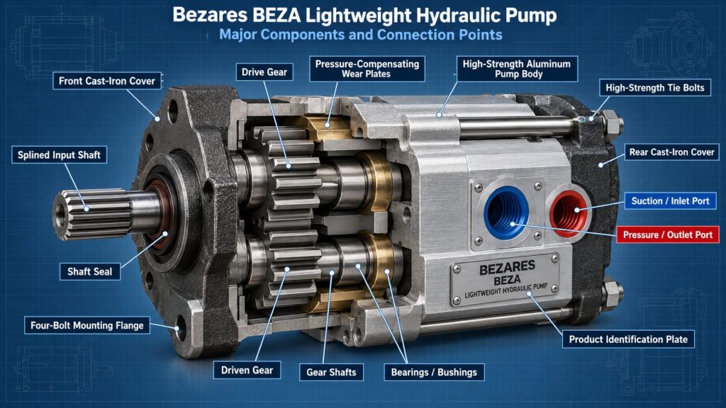
Major Components
- Aluminum gear housing
- Cast-iron front cover
- Cast-iron rear cover
- Drive gear
- Driven gear
- Drive shaft
- Bearing or bushing assemblies
- Pressure-compensation components
- Axial wear or pressure plates
- Shaft seal
- Housing seals
- Inlet port
- Pressure outlet port
- Mounting flange
- Identification plate or product markings
Product Type and Construction
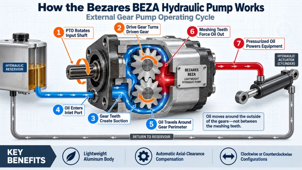
The BEZA is an external gear pump. Two meshing gears rotate inside a close-tolerance housing, carrying hydraulic fluid around the outside of the gears from the inlet side to the pressure outlet.
Its hybrid construction combines an aluminum center body with cast-iron covers. The aluminum body helps reduce total system weight, while the cast-iron end covers strengthen the areas that support mounting, shaft loads, and hydraulic pressure.
Automatic axial-clearance compensation helps maintain the designed relationship between the gears and pressure plates. This reduces internal leakage and supports consistent volumetric efficiency as system pressure changes.
How the Hydraulic Pump Works
A transmission PTO, engine drive, electric motor, or other mechanical source rotates the BEZA pump’s input shaft. The drive gear turns the second gear inside the housing.
As the gear teeth separate near the inlet, increasing cavity volume creates a low-pressure area that draws hydraulic fluid from the reservoir. Fluid becomes trapped between the gear teeth and housing and moves around the outside of the gears.
When the teeth mesh again near the outlet, the available volume decreases and forces fluid into the pressure line. A directional-control valve then routes the flow to a hydraulic cylinder, motor, stabilizer, lift mechanism, steering circuit, or other hydraulic function.
The pump creates flow rather than independently determining system pressure. Pressure rises when the connected equipment resists that flow. A correctly adjusted external relief valve is therefore required to protect the pump and system.
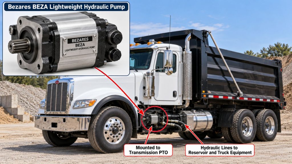
Position and Function Within the Vehicle
The BEZA pump can be installed at a PTO, engine-driven accessory location, electric power unit, or other approved mechanical drive. Its compact size makes it useful where frame space or component weight is limited.
Within the hydraulic circuit, the pump converts mechanical power into hydraulic flow. It works with a reservoir, suction line, pressure hose, relief valve, directional-control valve, filtration equipment, and hydraulic actuator.
The pump’s location must provide adequate support, hose clearance, shaft alignment, service access, and protection from road debris, exhaust heat, water intrusion, and physical damage.
Common Specifications
- Pump Type: Fixed-displacement external gear pump
- Housing Material: High-strength aluminum pump body
- Cover Material: Cast-iron front and rear covers
- Available Displacements: 6, 8, 10, 12, 14, and 16 cubic centimeters per revolution
- Maximum Pressure for 6–14 cc Models: 260 bar, approximately 3,770 psi
- Maximum Pressure for 16 cc Model: 240 bar, approximately 3,480 psi
- Maximum Speed: 3,000 rpm
- Rotation: Clockwise or counterclockwise
- Displacement Control: Fixed displacement
- Pressure Compensation: Automatic axial-clearance compensation within the pumping section
- Hydraulic Circuit: Open-circuit applications using an external reservoir, valves, and pressure protection
Maximum ratings and physical specifications depend on the exact BEZA configuration. Confirm the complete part number, mounting flange, shaft, ports, rotation, displacement, pressure requirement, and operating speed before ordering.
Displacement, Flow, Pressure, and Operating Capacity
The BEZA series is available in six nominal displacements. Larger displacement produces more theoretical flow per shaft revolution, while smaller models support lower-flow systems and may require less input power at the same speed and pressure.
- BEZA 6: 6 cc per revolution
- BEZA 8: 8 cc per revolution
- BEZA 10: 10 cc per revolution
- BEZA 12: 12 cc per revolution
- BEZA 14: 14 cc per revolution
- BEZA 16: 16 cc per revolution
At the published maximum speed of 3,000 rpm, theoretical flow ranges from approximately 18 liters per minute for the 6 cc pump to approximately 48 liters per minute for the 16 cc pump. Actual usable output is lower because of internal leakage and operating losses.
The 6 through 14 cc models have a published maximum pressure of 260 bar. The 16 cc model has a published maximum pressure of 240 bar. System design should normally provide operating margin below maximum component ratings.
Pump Speed, Rotation, and Drive Requirements
Bezares offers clockwise and counterclockwise BEZA configurations. Rotation must be determined while viewing the pump from the correct reference end specified by the manufacturer. An incorrectly rotating pump may fail to draw fluid and can damage its seals or internal components.
The drive system must keep pump speed within the published limit. For PTO-driven installations, the transmission speed, PTO ratio, and engine operating rpm must be calculated together.
The pump shaft and mounting arrangement must match the drive source. Misalignment, excessive side loading, an incorrect coupling, or inadequate spline engagement can damage the shaft, bearings, bushings, and seals.
Hydraulic Circuit and Equipment Integration
The BEZA requires external hydraulic-system components selected for its displacement, speed, pressure, and intended application. A complete system may include:
- Hydraulic-fluid reservoir
- Reservoir breather and fill cap
- Suction hose and fittings
- Pressure hose and fittings
- Pressure-relief valve
- Directional-control valve
- Return-line filter
- Hydraulic cylinder or motor
- Pressure gauge or electronic pressure sensor
- Temperature monitoring
- PTO or other mechanical drive
- Operating controls and safety interlocks
The smallest compatible pump is not always the correct choice. Pump displacement must provide the required equipment speed without forcing the drive system to operate continuously near its maximum rpm.
Ports, Hoses, and Flow Direction
The pump inlet must be connected to the reservoir, while the pressure outlet supplies the hydraulic control circuit. Port identity and flow direction should be confirmed using Bezares documentation for the exact part number.
The suction hose should be short, adequately sized, properly supported, and free from internal restrictions. Undersized fittings, excessive bends, clogged strainers, or deteriorated hose liners can restrict inlet flow and cause cavitation.
Pressure hoses, fittings, valves, and actuators must be rated for the system’s maximum pressure and temperature. Hose routing must protect the lines from abrasion, crushing, heat, twisting, and contact with moving equipment.
Controls and Electronic Integration
The BEZA is mechanically driven and does not contain an integrated electronic controller. System control normally comes from the PTO controls, directional valve, solenoids, air controls, manual levers, or an equipment-specific electronic control module.
Electronic integration may include PTO permission, engine-speed control, pressure monitoring, hydraulic-temperature monitoring, low-fluid warnings, interlocks, emergency stops, and body-position sensors.
Controls should prevent the pump from operating under unsafe conditions, including excessive engine speed, incorrect transmission status, low fluid level, or unintended equipment movement.
Efficiency, Heat, and Lubrication
Automatic axial-clearance compensation helps control internal leakage between the gear faces and pressure plates. This supports volumetric efficiency across changes in pressure and normal component wear.
Hydraulic heat is created by internal leakage, pressure drop, hose restriction, operation over the relief valve, and other system losses. A pump that is too large can circulate unnecessary flow and create additional heat, while a pump that is too small may require excessive operating speed.
The hydraulic fluid lubricates the gears, shaft-support components, and internal pressure surfaces. The pump must never be operated without an adequate supply of clean hydraulic fluid.
Duty Cycle and Operating Conditions
Acceptable duty cycle depends on displacement, pressure, speed, hydraulic-fluid temperature, reservoir capacity, filtration, cooling, and the limits of the driven equipment.
Maximum pressure and maximum speed should not automatically be treated as continuous operating targets. The hydraulic system should be designed with appropriate operating margin and evaluated for expected cycle length and frequency.
Cold starts, high ambient temperatures, contaminated environments, repeated relief-valve operation, and extended high-pressure cycles can shorten pump and fluid life.
Mounting and Installation
The BEZA must be installed using the correct flange, shaft connection, coupling, fasteners, and support arrangement. The mounting face should be clean, flat, and free from paint, burrs, or damage that could prevent proper alignment.
Direct-drive installations should avoid applying excessive axial or radial loads to the pump shaft. Remote-drive arrangements require correct driveline alignment, phasing, working angles, support, and guarding.
The inlet circuit should be filled and the pump correctly primed before startup. Initial operation should be conducted at low speed while technicians verify rotation, fluid supply, pressure, leakage, noise, and actuator movement.
PTO and Vehicle Compatibility
Compatibility depends on the vehicle, transmission, PTO, required pump rotation, mounting interface, available space, hydraulic demand, and equipment duty cycle.
The PTO must provide the required operating speed and torque without exceeding the pump’s limits. Higher pressure and higher flow both increase the power required from the transmission, PTO, coupling, and pump shaft.
The installation must preserve clearance from exhaust components, driveshafts, suspension parts, brake lines, electrical wiring, fuel-system components, and body equipment.
Hydraulic Fluid, Filtration, and Reservoir Compatibility
The hydraulic fluid must meet Bezares requirements for viscosity, lubricity, temperature stability, seal compatibility, and contamination control. The proper fluid varies with the application and operating climate.
The reservoir must provide sufficient fluid volume, air separation, cooling, thermal-expansion space, and an uninterrupted supply to the pump inlet. Its suction outlet should remain covered under all normal vehicle and equipment positions.
Filtration must control contamination without restricting inlet or return flow. Filter size, micron rating, dirt-holding capacity, bypass setting, and change interval should match the system’s flow and cleanliness requirements.
Common Applications
- Compact commercial-vehicle hydraulic systems
- Light- and medium-duty vocational trucks
- Utility and service vehicles
- Small dump bodies and tipping equipment
- Liftgates and loading equipment
- Vehicle-mounted cranes and stabilizers
- Recovery and towing equipment
- Material-handling equipment
- Agricultural machinery
- Industrial hydraulic power units
- Mobile maintenance equipment
- Auxiliary hydraulic circuits
Advantages
- Lightweight aluminum-body construction
- Cast-iron covers reinforce critical areas
- Compact size supports restricted installations
- Six displacement options allow closer system matching
- Clockwise and counterclockwise versions are available
- Maximum speed up to 3,000 rpm
- Pressure ratings suitable for many mobile hydraulic systems
- Automatic axial-clearance compensation supports efficiency
- Simple fixed-displacement gear-pump design
- Can be integrated with different PTO and auxiliary-drive systems
Limitations or Considerations
- Fixed displacement does not automatically adjust output to hydraulic demand
- Requires an external pressure-relief valve
- Maximum pressure is lower on the 16 cc model
- Rotation must be correctly matched to the drive system
- Incorrect PTO ratio can overspeed the pump
- Restricted inlet flow can quickly damage the pump
- Continuous high-pressure operation can create substantial heat
- Aluminum housing requires protection from mounting distortion and physical damage
- Ports, flange, and shaft must match the exact application
- System components must be selected for the pump’s possible flow and pressure
Driver and Operator Experience
Operators should experience predictable equipment movement when the pump, PTO ratio, valves, and actuators are correctly matched. Equipment speed should increase or decrease consistently with pump speed.
Unusual whining, rattling, vibration, jerky actuator movement, weak hydraulic performance, excessive heat, or visible leakage should be reported before continued operation causes additional damage.
The PTO or other drive should be disengaged when hydraulic power is no longer required. Operators should avoid unnecessary operation over the relief valve or at excessive engine speed.
PTO Engagement and Hydraulic Operating Procedure
Operators must follow the vehicle, transmission, PTO, hydraulic-equipment, and Bezares instructions. A general operating sequence includes:
- Park or position the vehicle according to the equipment manufacturer’s instructions.
- Apply the parking brake and place the transmission in the required operating condition.
- Verify that people and obstructions are clear of the hydraulic equipment.
- Engage the PTO or auxiliary drive using the approved procedure.
- Operate the engine at the specified hydraulic working speed.
- Activate the hydraulic control smoothly.
- Monitor equipment movement, hydraulic sound, pressure, and temperature.
- Return the control to neutral when the operation is complete.
- Disengage the PTO before moving the vehicle unless the system is specifically approved for mobile operation.
This overview does not replace manufacturer instructions, operator training, or employer safety procedures.
Inspection and Wear Points
- Aluminum gear housing
- Cast-iron front and rear covers
- Mounting flange
- Drive shaft and coupling
- Shaft seal
- Housing seals
- Mounting bolts
- Inlet and outlet fittings
- Suction hose
- Pressure and return hoses
- Reservoir mounts and breather
- Hydraulic-fluid level and condition
- Filters and restriction indicators
- PTO or auxiliary-drive mounting
- Control valves and relief valve
- Hydraulic cylinders and motors
Lubrication Requirements
The BEZA’s internal gears, shaft-support components, pressure plates, and sealing surfaces depend on hydraulic fluid for lubrication. The pump must not be started dry.
The suction circuit should be filled and the pump primed according to Bezares instructions before initial operation or after repairs that drain the pump and inlet hose.
External PTO shafts, universal joints, or couplings should be lubricated according to their manufacturers’ requirements. Lubricants must not contaminate the hydraulic fluid or pump ports.
Maintenance and Ownership Notes
Routine service should include checking hydraulic-fluid level, inspecting the pump and hoses for leaks, servicing filters, cleaning the reservoir breather, and monitoring system temperature and operating speed.
Changes in noise or equipment speed can provide early warning of suction restriction, aeration, contamination, internal wear, or drive-system problems.
Replacement seals, shafts, covers, or complete pumps should be matched using the exact Bezares part number. Similar-looking BEZA pumps may have different displacement, rotation, mounting, shaft, or port configurations.
Hydraulic-fluid and filter intervals should reflect the equipment manufacturer’s schedule and actual operating environment. High-cycle, dusty, wet, or extreme-temperature service may require shorter intervals.
Common Hydraulic-Pump and System Problems
- No hydraulic flow: Incorrect rotation, an unengaged PTO, broken coupling, empty reservoir, blocked inlet, lost prime, or internal pump damage may prevent flow.
- Low output flow: Low drive speed, internal wear, suction restriction, aerated fluid, excessive temperature, incorrect displacement, or system leakage may reduce output.
- Pump noise or cavitation: Low fluid level, a restricted suction hose, clogged breather, cold high-viscosity fluid, excessive pump speed, or air entering the inlet circuit may cause noise.
- Excessive hydraulic heat: Continuous relief-valve operation, undersized hoses, excessive flow, contaminated fluid, restricted filters, internal leakage, or an undersized reservoir may create heat.
- Shaft-seal leakage: Excessive inlet vacuum, high case pressure, shaft misalignment, worn coupling components, heat, contamination, or seal damage may cause leakage.
- Jerky equipment movement: Air in the system, low fluid level, valve contamination, unstable pump speed, a damaged actuator, or restricted plumbing may interrupt flow.
- Repeated relief-valve operation: Overloading, incorrect valve adjustment, obstructed equipment movement, excessive pump flow, or an undersized control circuit may force the system over relief.
- Mounting or coupling failure: Misalignment, loose fasteners, mounting distortion, excessive shaft loads, vibration, or an incorrect drive connection may damage the pump and drive system.
Safety and Service Precautions
Lower or mechanically support all raised equipment before inspecting or repairing the hydraulic system. Hydraulic pressure must never be relied upon as the sole support for a raised body, boom, platform, or attachment.
Disengage the PTO, shut down the engine, secure the vehicle, and relieve stored hydraulic pressure before disconnecting hoses or components. Hot hydraulic fluid and system parts can cause serious burns.
Never use a hand to search for a hydraulic leak. High-pressure fluid can penetrate skin and requires immediate emergency medical treatment.
Rotating PTO shafts and couplings require proper guards. Keep hands, clothing, tools, and service equipment away from the drive whenever the engine can operate.
Identification Information
Identification information may be printed, stamped, or displayed on a label attached to the pump. Record the complete information before ordering service components or a replacement unit.
- Bezares manufacturer name
- BEZA series designation
- Complete product or part number
- Nominal displacement
- Clockwise or counterclockwise rotation
- Mounting-flange type
- Drive-shaft configuration
- Inlet and outlet port types
- Maximum pressure and speed
- PTO or drive-system model
- Vehicle identification number
- Hydraulic-equipment manufacturer and model
Buying Considerations
- Calculate the hydraulic flow required by the equipment
- Select the correct displacement
- Verify maximum operating pressure
- Confirm clockwise or counterclockwise rotation
- Match the mounting flange
- Match the drive shaft or spline
- Confirm inlet and outlet port types
- Calculate pump speed at the intended engine or motor speed
- Verify PTO torque and horsepower capacity
- Check available installation space
- Size the reservoir and hoses for the expected flow
- Select properly rated valves and filters
- Confirm hydraulic-fluid requirements
- Compare continuous and intermittent duty requirements
- Use an installer familiar with mobile hydraulic systems
Variants and Configurations
- BEZA 6 cc pump
- BEZA 8 cc pump
- BEZA 10 cc pump
- BEZA 12 cc pump
- BEZA 14 cc pump
- BEZA 16 cc pump
- Clockwise rotation
- Counterclockwise rotation
- Application-specific mounting arrangements
- Application-specific shaft and port configurations
Comparison to Similar Equipment
Compared with the Permco P5151 Hydraulic Pump, the BEZA is a smaller-displacement lightweight pump intended for more compact hydraulic circuits. The P5151 is a larger cast-iron gear-pump family used in higher-flow vocational applications.
Compared with the Muncie E Series Hydraulic Pump, the BEZA offers a compact aluminum-body design with displacement options beginning at 6 cc per revolution.
Compared with the Parker F1 Hydraulic Pump, the BEZA uses an external gear design rather than a bent-axis piston design. The Parker F1 generally serves larger truck-hydraulic applications requiring substantially more displacement and flow.
Compared with a variable-displacement pump, the BEZA delivers a fixed amount of theoretical flow per revolution. It is mechanically simpler but cannot automatically reduce displacement as hydraulic demand changes.
Best Fit For
- Compact mobile hydraulic systems
- Applications requiring 6 to 16 cc per revolution
- Installations where pump weight matters
- Space-restricted commercial vehicles
- Small hydraulic cylinders and motors
- Light- and medium-duty vocational equipment
- Systems requiring clockwise or counterclockwise rotation
- Operators seeking a compact fixed-displacement gear pump
- Vehicles originally equipped with a compatible BEZA configuration
Related Vehicle and Trailer Types
- Complete Guide to Semi Truck Types
- Class 6 vs Class 7 vs Class 8 Trucks
- Vocational Trucks
- Utility Trucks
- Service Trucks
- Dump Trucks
- Recovery Vehicles
- Municipal Trucks
Related Truck and Trailer Models
- Freightliner M2 106
- Freightliner 108SD
- International CV Series
- International MV Series
- Kenworth T280
- Peterbilt 536
- Mack MD Series
- Ford F-650
- Ford F-750
Related PTO and Hydraulic System Types
- Power Take-Off Systems
- Hydraulic Pumps & Motors
- Wet Kits & Complete Hydraulic Systems
- Hydraulic Cylinders & Dump Hoists
- Hydraulic Valves, Controls & Reservoirs
- Hydraulic Hoses, Fittings & Filtration
- Fixed-Displacement Gear Pumps
- Mobile Hydraulic Power Systems
Related PTO and Hydraulic Products
- Parker F1 Hydraulic Pump
- Parker F2 Twin-Flow Hydraulic Pump
- Muncie E Series Hydraulic Pump
- Permco P5151 Hydraulic Pump
- Permco DM-640 Dump Pump
- Muncie WETLINE Hydraulic System
- Parker Chelsea Wetline Hydraulic System
- Muncie CS6 Series Power Take-Off
- Muncie TG Series Power Take-Off
- Muncie FR6Q Power Take-Off
Related Equipment Systems
- PTO & Hydraulic Systems
- Transmissions
- Electrical Systems
- Suspension Systems
- Axles & Differentials
- Brake Systems
- Tires & Wheels
Related Guides
- PTO & Hydraulic System Guides
- How Commercial Truck PTO and Hydraulic Systems Work
- Commercial Truck Power Take-Off Types Explained
- How to Choose a PTO and Hydraulic Pump
- Commercial Truck Wet Kits Explained
- How to Inspect and Maintain Truck Hydraulic Systems
- Fixed vs Variable-Displacement Hydraulic Pumps
- How to Size a Hydraulic Pump for a Commercial Truck
Regulatory and Compliance Notes
The pump’s flow and pressure ratings do not increase the vehicle’s certified gross vehicle weight rating, gross axle weight ratings, payload capacity, or legal operating weight.
The completed installation must preserve safe operation of the transmission, PTO, brakes, steering, electrical system, suspension, exhaust, fuel system, and vehicle frame.
Hydraulic hoses, fittings, valves, and actuators must carry appropriate pressure and temperature ratings. Rotating PTO shafts, couplings, and remote drives require suitable guarding.
Installers and operators must follow applicable vehicle, workplace, equipment, and environmental requirements for hydraulic-fluid containment and disposal.
Real World Operating Notes
Selecting the correct displacement is more important than simply choosing the largest BEZA model. Excessive pump flow can make equipment difficult to control, waste engine power, and generate unnecessary heat.
A pump that appears weak may be responding to a restricted suction hose, clogged breather, worn control valve, leaking actuator, incorrect PTO speed, or relief valve set too low. The complete hydraulic system should be tested before the pump is replaced.
Because the BEZA has an aluminum body, mounting bolts should be tightened according to the specified sequence and torque. Uneven or excessive tightening can distort the housing or mounting flange.
The published 3,000-rpm maximum should not be treated as the correct operating speed for every installation. Pump speed should be selected around the required flow, expected pressure, hydraulic temperature, and service duty.
Frequently Asked Questions
What is the Bezares BEZA Hydraulic Pump?
The BEZA is a compact fixed-displacement external gear pump with a high-strength aluminum body and cast-iron front and rear covers.
Why is the BEZA described as lightweight?
Its main pump body is made from high-strength aluminum instead of using an entirely cast-iron housing.
What displacements are available?
Bezares lists 6, 8, 10, 12, 14, and 16 cc-per-revolution configurations.
What is the maximum operating pressure?
The 6 through 14 cc models have a published maximum pressure of 260 bar. The 16 cc model has a published maximum pressure of 240 bar.
What is the maximum pump speed?
Bezares publishes a maximum speed of 3,000 rpm for the listed BEZA displacement options.
Is the BEZA available in both rotations?
Yes. Bezares lists clockwise and counterclockwise configurations.
Does the BEZA include a control valve?
The BEZA is a hydraulic gear pump. Directional valves, pressure relief, reservoir equipment, filtration, and operating controls are normally selected separately for the complete system.
Can the BEZA be driven by a truck PTO?
It can be used with an appropriately matched drive system when the PTO ratio, rotation, shaft, mounting interface, torque capacity, and operating speed are compatible.
Why is correct pump rotation important?
Incorrect rotation prevents normal inlet-to-outlet flow and may cause loss of prime, seal failure, poor lubrication, or internal pump damage.
How can the correct replacement pump be identified?
Use the complete Bezares part number, displacement, rotation, mounting flange, shaft, ports, pressure requirement, and drive-system information.
Availability and Where to Find
Bezares BEZA pumps may be available through Bezares distributors, Eaton mobile-power channels in supported markets, commercial-truck equipment installers, hydraulic-system specialists, PTO suppliers, and industrial hydraulic distributors.
Availability depends on the required displacement, rotation, shaft, mounting flange, port configuration, and regional distribution. Buyers should obtain a configuration-specific quotation rather than ordering solely by the BEZA series name.
Current product information, technical support, and distributor resources are available through the Bezares BEZA Lightweight Hydraulic Pump page and the Bezares Gear Pump product family.
Support Trucking Families
Truck Equipment Atlas supports the mission of Grey Cross, a nonprofit dedicated to helping families of truck drivers who lose their lives while on the road. As the site grows, part of its mission is to bring awareness and support to these families.
Podcast or Video Section
Learn More Through Audio and Video
Truck Equipment Atlas will continue expanding with podcast episodes, interviews, and equipment breakdowns to help drivers and fleets better understand trucks and equipment.
Follow the Growth of Truck Equipment Atlas
Truck Equipment Atlas continues to expand with new truck profiles, trailer coverage, diesel engine pages, equipment system resources, manufacturer information, and educational guides.
Visit our Site Updates page to explore recent additions, project milestones, and upcoming resources as we continue building one of the industry’s growing commercial trucking equipment reference libraries.
View the Latest Site Updates: Truck Equipment Atlas Site Updates