
Quick Facts
- Manufacturer: Parker Hannifin
- Product Series: F1
- Product Type: Fixed-displacement bent-axis axial-piston hydraulic pump
- Primary Market: Commercial truck and mobile hydraulic equipment
- Available Displacements: 25.6, 40.9, 51.1, 59.9, 81.6, and 102.9 cubic centimeters per revolution
- Maximum Operating Pressure: Up to 400 bar or approximately 5,800 psi
- Maximum Published Flow: Up to 216 liters per minute, depending on displacement
- Maximum Shaft Speed: Up to 3,100 rpm, depending on pump size and operating condition
- Maximum Self-Priming Speed: Up to 3,050 rpm, depending on pump size and inlet conditions
- Rotation Options: Right-hand and left-hand rotation
- Approximate Weight: 8.5 or 12.5 kilograms, depending on model
- Primary Applications: Cargo cranes, forestry cranes, hook loaders, skip loaders, dump equipment, and multipurpose vocational vehicles
- Production Status: Current product family
Overview
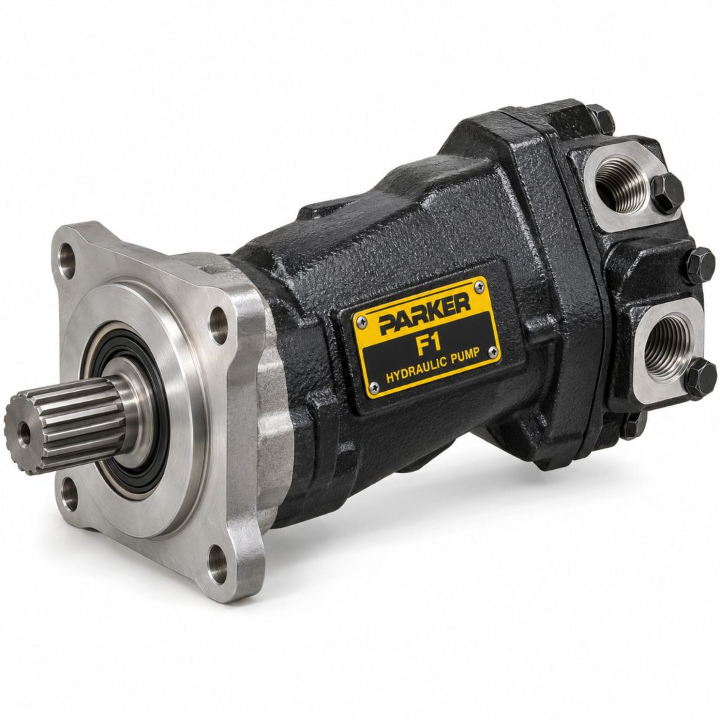
The Parker F1 is a fixed-displacement bent-axis axial-piston pump developed for commercial trucks and other mobile hydraulic equipment. It converts mechanical power from a power take-off into hydraulic flow for cranes, hoists, hook loaders, dump systems, forestry equipment, and other vocational machinery.
The F1 Series combines high operating pressure, strong self-priming capability, compact installation dimensions, low weight, and high overall efficiency. Its bent-axis piston design is intended to provide dependable performance in truck applications where available mounting space is limited and equipment cycles can place substantial demands on the hydraulic system.
Six displacement sizes are available, ranging from 25.6 to 102.9 cubic centimeters per revolution. Each size is offered in right-hand and left-hand rotation configurations, allowing the pump to be matched to the rotation of the selected PTO.
The exact F1 model must be selected according to the required hydraulic flow, operating pressure, pump speed, PTO ratio, direction of rotation, mounting interface, inlet conditions, and duty cycle.
Key Characteristics
- Fixed-displacement hydraulic pump
- Bent-axis axial-piston construction
- Designed for commercial-truck hydraulic systems
- Operating pressure up to 400 bar
- Six displacement sizes
- Right-hand and left-hand rotation options
- High self-priming speeds
- High overall hydraulic efficiency
- Compact installation dimensions
- Relatively low weight
- Low operating-noise characteristics
- Suitable for direct mounting to compatible PTOs
- Supports high-pressure vocational equipment
- Designed for open-circuit hydraulic systems
Major Components
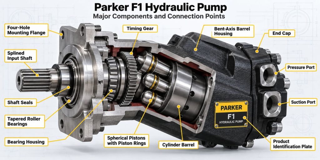
- Pump housing
- Input shaft
- Shaft bearings
- Cylinder barrel
- Axial pistons
- Piston shoes
- Bent-axis rotating group
- Port plate
- Pressure outlet port
- Suction inlet port
- Shaft seal
- Housing seals
- Mounting flange
- Internal lubrication passages
- Retaining hardware
Product Type and Construction
The F1 is a positive-displacement axial-piston pump with a fixed bent-axis geometry. Its displacement is determined by the size and arrangement of its piston rotating group and cannot be varied while the pump is operating.
As the input shaft rotates, the angled relationship between the shaft and cylinder barrel causes the pistons to move through alternating intake and pressure strokes. This design produces hydraulic flow with relatively high volumetric and mechanical efficiency.
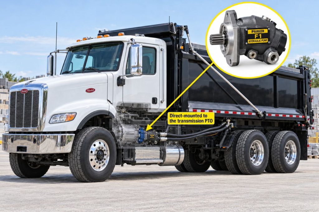
The pump’s compact housing allows it to be installed directly on a compatible PTO when the output interface, shaft, mounting flange, rotation, and chassis clearance are correct.
How the Hydraulic Pump Works
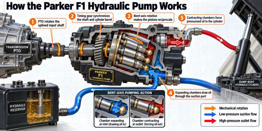
A transmission-mounted PTO rotates the F1 input shaft. That rotation turns the pump’s internal cylinder barrel and piston assembly.
During the intake portion of each piston’s movement, hydraulic fluid is drawn from the reservoir through the suction port. As the rotating group continues to turn, the piston moves inward and forces the trapped fluid through the pressure outlet.
Because the F1 is a fixed-displacement pump, it moves approximately the same theoretical volume of fluid during every shaft revolution. Hydraulic flow therefore increases or decreases with pump speed.
System resistance creates hydraulic pressure. The pump supplies flow, while the load, valves, actuators, hoses, and pressure-control system determine how much pressure is required.
Position and Function Within the Vehicle
The Parker F1 normally mounts to a compatible PTO attached to the truck’s transmission. It may be positioned beside or below the transmission, depending on the PTO opening, output arrangement, chassis, drivetrain, and available clearance.
The pump’s function is to convert rotary mechanical power into hydraulic flow. That flow is directed through valves to cylinders, motors, hoists, cranes, winches, or other hydraulic equipment.
The pump must be supported, plumbed, and positioned so movement of the powertrain does not cause interference with the frame, exhaust system, driveshaft, suspension, tanks, or body equipment.
Common Specifications
- Pump design: Fixed-displacement bent-axis axial-piston pump.
- F1-25 displacement: 25.6 cubic centimeters per revolution.
- F1-41 displacement: 40.9 cubic centimeters per revolution.
- F1-51 displacement: 51.1 cubic centimeters per revolution.
- F1-61 displacement: 59.9 cubic centimeters per revolution.
- F1-81 displacement: 81.6 cubic centimeters per revolution.
- F1-101 displacement: 102.9 cubic centimeters per revolution.
- Maximum operating pressure: 400 bar or approximately 5,800 psi.
- Maximum published flow range: 78 to 216 liters per minute, depending on model.
- Maximum shaft-speed range: 2,300 to 3,100 rpm, depending on model and operating condition.
- Maximum self-priming-speed range: 2,100 to 3,050 rpm, depending on model and inlet condition.
- Rotation: Right-hand or left-hand.
- Approximate weight: 8.5 kilograms for F1-25 through F1-61 models and 12.5 kilograms for F1-81 and F1-101 models.
Published maximum values depend on pump size, inlet pressure, oil viscosity, operating time, and other test conditions. The complete Parker data for the selected model should be used when engineering the hydraulic system.
Displacement, Flow, Pressure, and Operating Capacity
The F1 Series covers displacements from 25.6 through 102.9 cubic centimeters per revolution. A larger displacement produces more theoretical flow during each shaft revolution but also requires more input torque at a given hydraulic pressure.
Published maximum flow values range from 78 liters per minute for the F1-25 to 216 liters per minute for the F1-101. Actual delivered flow is affected by shaft speed, fluid viscosity, temperature, pressure, inlet conditions, and pump wear.
Operating pressure can reach 400 bar in properly engineered applications. However, the pump, PTO, transmission, hydraulic hoses, valves, cylinders, fittings, reservoir, and driven equipment must all be rated for the selected pressure.
The hydraulic system’s pressure-relief valve must be set low enough to protect the weakest component. The pump should not be used as the device that limits system pressure.
Intended PTO and Mounting Position
The F1 is intended for use with a compatible truck PTO capable of supporting the pump’s speed, torque, horsepower, shaft, flange, rotation, and weight.
The selected PTO ratio must allow the pump to reach the required flow without exceeding the maximum shaft or self-priming speed. The pump should normally operate within an efficient speed range rather than depending on maximum engine rpm.
Direct mounting creates a compact installation, but the combined pump, fittings, hoses, and fluid weight may require a support bracket. Chassis movement and powertrain vibration must not be allowed to fatigue the PTO housing or pump flange.
Bent-Axis Piston Design
The F1’s bent-axis design positions the cylinder barrel at an angle to the input shaft. As the assembly rotates, the angled geometry produces the piston movement needed to draw in and discharge hydraulic fluid.
This construction supports high pressure, high efficiency, and relatively high operating speeds in a compact package. It also helps the F1 provide strong self-priming performance when the inlet system is correctly designed.
Precision internal components require clean hydraulic fluid and dependable lubrication. Contamination, aeration, cavitation, or operation without oil can quickly damage the piston group, bearings, and port surfaces.
PTO Speed and Pump Rotation
The pump’s rotational direction must match the PTO output. Parker offers right-hand and left-hand F1 models, identified by the R or L designation in the product description.
Installing a pump with the wrong rotation can prevent normal fluid delivery and may cause immediate damage. Rotation should be confirmed while viewing the pump from the correct reference position defined by Parker.
Pump speed is determined by engine rpm, transmission PTO-drive gearing, and the PTO’s internal ratio. The selected combination must remain within the speed limit of the specific F1 displacement.
Hydraulic Circuit and Equipment Integration
The Parker F1 normally operates as part of an open-circuit hydraulic system containing:
- Hydraulic reservoir
- Suction hose and fittings
- Pressure hose
- Return hose
- Directional-control valve
- Pressure-relief valve
- Return and pressure filtration where required
- Hydraulic cylinders or motors
- Oil cooler where required
- Pressure and temperature monitoring
- Operator controls and equipment interlocks
The pump, PTO, valves, reservoir, hoses, and actuators must be designed as a complete system. Selecting components individually without considering total flow, pressure, heat, and duty cycle can result in poor performance or premature failure.
Inlet, Outlet, and Port Design
The suction port connects the pump to the hydraulic reservoir. The inlet hose should be large, short, properly routed, and resistant to collapse. Restrictions on the suction side can cause cavitation even when the reservoir contains enough fluid.
The pressure outlet carries hydraulic flow to the control valve or another system component. Pressure hoses, tubes, fittings, and valves must be rated for the system’s maximum pressure and expected pressure spikes.
Hoses should be routed away from exhaust components, sharp edges, rotating shafts, and suspension movement. The plumbing must also accommodate normal engine and transmission movement.
Controls and Electronic Integration
The F1 itself is a mechanically driven fixed-displacement pump and normally does not contain an electronic displacement controller. Hydraulic flow begins whenever the PTO engages and rotates the pump.
Electronic and pneumatic control functions may instead be provided by:
- PTO engagement controls
- Engine-speed controls
- Hydraulic directional valves
- Proportional valve controllers
- Pressure switches
- Temperature switches
- Body-equipment interlocks
- Emergency-stop systems
- Remote-control systems
- Vehicle or equipment control modules
Because the F1 produces flow whenever it rotates, the control-valve arrangement must safely manage flow when the driven equipment is not moving.
Efficiency, Heat, and Lubrication
The bent-axis piston design provides high overall efficiency, which helps reduce wasted engine power and unnecessary heat. Efficiency still changes with speed, pressure, temperature, fluid condition, and internal wear.
The hydraulic fluid lubricates the pump’s pistons, bearings, rotating group, and internal contact surfaces. Operating with insufficient fluid, contaminated oil, excessive aeration, or unsuitable viscosity can cause rapid damage.
Heat generated by the pump, valves, actuators, and pressure losses must be removed through the reservoir, plumbing, and an oil cooler when required. Continuously routing full flow across a relief valve creates substantial heat and wastes power.
Duty Cycle and Operating Conditions
The proper F1 size depends on operating pressure, pump speed, cycle duration, ambient temperature, hydraulic-fluid temperature, inlet condition, and the amount of time the system operates at high load.
Some published maximum input-power ratings apply only for brief periods. Parker identifies certain maximum power values as being limited to six seconds during any one-minute period.
Cold hydraulic fluid increases suction restriction and input torque. The system should be warmed at reduced speed and pressure before heavy operation in low temperatures.
High ambient temperatures, long cycles, high pressure, and insufficient reservoir capacity can require additional cooling or a lower operating load.
Mounting and Installation
The F1 must be installed with the correct mounting flange, input shaft, direction of rotation, PTO output, and chassis orientation. Installation should follow Parker’s instructions for the selected model.
The installer should verify:
- Correct pump displacement
- Correct direction of rotation
- Compatible PTO flange and shaft
- Approved PTO torque and power capacity
- Maximum pump speed
- Pump and frame clearance
- Required pump support
- Suction-hose size and routing
- Pressure-hose rating
- Reservoir placement and capacity
- Relief-valve setting
- Filter placement and capacity
- Hydraulic-fluid specification
- Proper system priming before startup
The pump should not be started dry. The hydraulic circuit must be filled, vented, and checked according to Parker and equipment-manufacturer procedures before normal operation begins.
PTO and Vehicle Compatibility
The Parker F1 can be used with compatible PTOs from Parker Chelsea, Muncie, and other approved manufacturers when the mechanical interface and performance ratings match.
Compatibility depends on:
- PTO manufacturer and model
- PTO output flange and shaft
- PTO rotation
- PTO ratio
- Available output torque and horsepower
- Transmission PTO-drive ratio
- Engine operating speed
- Vehicle frame and driveline clearance
- Pump weight and support
- Hydraulic-equipment requirements
A PTO should not be selected only because its output physically connects to the pump. Its torque, horsepower, speed, duty-cycle, and lubrication ratings must also be sufficient.
Hydraulic Fluid, Filtration, and Reservoir Compatibility
The hydraulic fluid should provide the viscosity, lubrication, oxidation resistance, anti-wear protection, and temperature performance required by Parker and the other system components.
The reservoir should provide adequate usable volume, fluid cooling, air separation, contamination settlement, and thermal expansion space. Its location should support dependable pump inlet conditions.
Filters must maintain the required fluid cleanliness without creating excessive inlet or return restriction. A suction strainer should only be used when its sizing and maintenance requirements prevent pump starvation.
Water, dirt, metal particles, incorrect fluid, and mixed incompatible oils can damage the pump and shorten the life of valves and actuators.
Common Applications
- Cargo cranes
- Knuckle-boom cranes
- Forestry cranes
- Hooklift trucks
- Skip loaders
- Dump trucks
- Dump trailers powered by tractor wet kits
- Roll-off trucks
- Utility trucks
- Service trucks
- Recovery vehicles
- Hydraulic winches
- Municipal vehicles
- Construction equipment
- Multipurpose vocational trucks
Advantages
- Operating pressure up to 400 bar
- High self-priming capability
- High overall efficiency
- Compact installation dimensions
- Relatively low pump weight
- Low operating-noise characteristics
- Six displacement choices
- Right-hand and left-hand rotation options
- Suitable for direct PTO mounting
- High flow capability in larger models
- Designed specifically for truck hydraulics
- Supports many vocational applications
- Current manufacturer support and technical literature
Limitations or Considerations
- Fixed displacement cannot automatically adjust to changing flow demand
- Flow changes directly with pump speed
- Incorrect rotation can damage the pump
- Maximum speed decreases on larger displacement models
- Requires clean hydraulic fluid
- Sensitive to suction restriction and cavitation
- Must be properly primed before operation
- PTO capacity must match pump demand
- High-pressure operation increases required input torque
- Continuous relief-valve operation creates excessive heat
- Direct-mounted installations may require pump support
- Chassis clearance must be checked before installation
- Some maximum ratings apply only for limited durations
Driver and Operator Experience
The operator normally controls the F1 by engaging or disengaging the truck’s PTO. Once the PTO is engaged, pump speed follows engine speed and the PTO ratio.
Hydraulic equipment should respond smoothly and predictably. Slow movement, jerking, unusual pump noise, foamy fluid, excessive temperature, or reduced lifting capacity may indicate a hydraulic-system problem.
Operators should avoid unnecessary high engine speed. The lowest engine speed that provides adequate hydraulic performance generally reduces noise, heat, fuel consumption, and component wear.
PTO Engagement and Hydraulic Operating Procedure
The exact procedure depends on the vehicle, PTO, and hydraulic equipment. A general operating sequence may include:
- Position and secure the vehicle as required.
- Inspect the hydraulic system for leaks or damage.
- Confirm that the hydraulic-fluid level is correct.
- Place the transmission and vehicle controls in the approved PTO mode.
- Reduce engine speed to the approved engagement range.
- Engage the PTO.
- Allow the pump and hydraulic fluid to warm at reduced load when necessary.
- Operate the equipment within approved pressure and speed limits.
- Monitor noise, pressure, temperature, and equipment movement.
- Return the engine to the required speed before disengagement.
- Place the hydraulic controls in the approved neutral position.
- Disengage the PTO and confirm that the equipment has stopped.
This general sequence does not replace the instructions supplied by Parker, the PTO manufacturer, the vehicle builder, or the equipment manufacturer.
Inspection and Wear Points
- Pump housing
- Input shaft and spline
- Mounting flange
- PTO-to-pump connection
- Pump-support bracket
- Shaft seal
- Housing seals
- Suction hose and fittings
- Pressure hose and fittings
- Hydraulic-fluid condition
- Reservoir level
- Filter indicators
- Pressure-relief valve
- Operating temperature
- Unusual noise or vibration
- Frame, exhaust, and driveline clearance
Lubrication Requirements
The F1 is lubricated by the hydraulic fluid circulating through the pump. Clean oil of the correct type and viscosity must reach the rotating group immediately after startup.
The pump should be filled or primed according to Parker’s installation procedure. Dry starting can damage the piston group, bearings, and sealing surfaces within seconds.
The hydraulic-fluid level must remain high enough to prevent the pump from drawing air. Oil should be changed according to fluid condition, contamination level, operating environment, and equipment-manufacturer requirements.
Maintenance and Ownership Notes
Inspect the F1 and its hydraulic system regularly for leakage, loose mounting hardware, damaged hoses, excessive temperature, unusual noise, and contaminated fluid.
Filter elements should be serviced before restriction causes bypass operation or pump starvation. Reservoir breathers should also be maintained so contaminated air is not drawn into the system.
Any recurring shaft-seal leak should be diagnosed rather than treated only as a seal problem. Misalignment, excessive case pressure, a damaged shaft, heat, contamination, or unsupported pump weight may contribute to leakage.
Before replacing a failed pump, inspect the reservoir, hoses, relief valve, filtration, PTO, and driven equipment. Contamination left in the system can quickly damage a replacement F1.
Common Pump and Hydraulic-System Problems
- Pump does not produce flow: Incorrect rotation, a disengaged PTO, broken input connection, empty reservoir, blocked suction line, trapped air, or internal pump damage may prevent flow.
- Cavitation noise: A restricted or undersized suction hose, cold oil, low reservoir level, clogged breather, excessive speed, or collapsed inlet hose may cause cavitation.
- Aerated hydraulic fluid: A leaking suction connection, low oil level, poor return-line placement, excessive return velocity, or inadequate reservoir design may allow air into the fluid.
- Low hydraulic pressure: Pump wear, relief-valve problems, internal valve leakage, cylinder leakage, incorrect pump speed, or excessive system demand may reduce pressure.
- Slow equipment movement: Low engine speed, insufficient displacement, pump wear, suction restriction, valve leakage, or excessive load may reduce flow.
- Hydraulic system overheats: Continuous relief-valve operation, excessive pressure loss, undersized plumbing, an insufficient reservoir, internal leakage, or an excessive duty cycle may generate heat.
- Shaft-seal leakage: Seal wear, contamination, excessive case pressure, shaft damage, misalignment, heat, or unsupported pump weight may cause leakage.
- PTO or driveline failure: An oversized pump, excessive hydraulic pressure, incorrect PTO ratio, pump seizure, or pressure spikes may overload the mechanical drive.
Safety and Service Precautions
Never install or service the pump with the engine running. Disengage the PTO, remove the ignition key, secure the vehicle, chock the wheels, and prevent anyone from starting the truck.
Raised dump bodies, cranes, hoists, and other hydraulic equipment must be mechanically blocked before anyone works beneath them. Hydraulic pressure alone must not be used to support raised equipment.
Release hydraulic pressure before loosening hoses, fittings, valves, or pump components. High-pressure hydraulic fluid can penetrate skin and cause serious injury.
Never search for a hydraulic leak with bare hands. Use an appropriate inspection method and obtain immediate medical treatment for any suspected fluid-injection injury.
Identification Information
The pump identification label should be used to confirm its displacement, direction of rotation, part number, and production information.
- Parker F1 series designation
- Complete pump model
- Parker part number
- Pump displacement
- Right-hand or left-hand rotation
- Maximum operating pressure
- Maximum permitted speed
- Mounting-flange configuration
- Input-shaft specification
- Port sizes and arrangement
- PTO manufacturer and model
- Hydraulic-fluid specification
- Vehicle and equipment application
A pump should not be identified solely by appearance. Different F1 models can use similar housings while having different displacement, rotation, speed, torque, and flow characteristics.
Buying Considerations
- Calculate the hydraulic flow required by the equipment.
- Confirm the required operating pressure.
- Select the appropriate F1 displacement.
- Determine the pump speed produced by the PTO and engine.
- Confirm right-hand or left-hand rotation.
- Match the PTO output flange and shaft.
- Verify PTO torque and horsepower capacity.
- Confirm the required duty cycle.
- Check the pump’s maximum shaft and self-priming speeds.
- Measure available chassis clearance.
- Determine whether a pump-support bracket is required.
- Size the reservoir and suction plumbing correctly.
- Confirm hose, valve, and cylinder pressure ratings.
- Plan appropriate filtration and cooling.
- Use a qualified truck-hydraulic installer.
Variants and Configurations
- F1-25-R right-hand rotation
- F1-25-L left-hand rotation
- F1-41-R right-hand rotation
- F1-41-L left-hand rotation
- F1-51-R right-hand rotation
- F1-51-L left-hand rotation
- F1-61-R right-hand rotation
- F1-61-L left-hand rotation
- F1-81-R right-hand rotation
- F1-81-L left-hand rotation
- F1-101-R right-hand rotation
- F1-101-L left-hand rotation
Comparison to Similar Equipment
Compared with the future Parker F2 Twin-Flow Hydraulic Pump, the F1 supplies a single hydraulic flow from one fixed-displacement pumping section. The F2 provides two separate flows for applications requiring independent hydraulic circuits.
Compared with the future Muncie E Series Hydraulic Pump, the Parker F1 uses a bent-axis axial-piston design intended for high-pressure truck hydraulics. The correct choice depends on pressure, displacement, speed, mounting, PTO, and equipment requirements.
Compared with the future Permco P5151 Hydraulic Pump, the F1 uses piston-pump construction rather than a conventional external-gear design. Piston pumps can support high pressure and efficiency, while gear pumps may offer simpler construction for suitable applications.
Compared with the future Parker VP1 Variable-Displacement Hydraulic Pump, the F1 delivers fixed displacement per revolution. The VP1 can vary displacement according to system demand in properly configured load-sensing systems.
Best Fit For
- Commercial trucks requiring high-pressure hydraulics
- Cargo and knuckle-boom cranes
- Forestry cranes
- Hooklift and skip-loader systems
- Dump trucks and wet-kit applications
- Roll-off trucks
- Utility and service vehicles
- Applications requiring a compact direct-mounted pump
- Systems needing fixed hydraulic flow per revolution
- Vehicles with correctly matched PTO speed and rotation
- Applications requiring right-hand or left-hand pump rotation
- Operators with appropriate hydraulic-service support
Related Vehicle and Trailer Types
- Complete Guide to Semi Truck Types
- Class 6 vs Class 7 vs Class 8 Trucks
- Dump Trucks
- Hooklift Trucks
- Roll-Off Trucks
- Crane Trucks
- Utility Trucks
- Service Trucks
- Logging Trucks
- Dump Trailers
Related Truck and Trailer Models
- Freightliner M2 106
- Freightliner 114SD
- International HX Series
- Kenworth T280
- Kenworth T880
- Peterbilt 536
- Peterbilt 567
- Mack Granite
- Volvo VHD
- Western Star 47X
Related PTO and Hydraulic System Types
- Hydraulic Pumps & Motors
- Power Take-Off Systems
- Wet Kits & Complete Hydraulic Systems
- Hydraulic Cylinders & Dump Hoists
- Hydraulic Valves, Controls & Reservoirs
- Hydraulic Hoses, Fittings & Filtration
Related PTO and Hydraulic Products
- Parker F2 Twin-Flow Hydraulic Pump
- Parker VP1 Variable-Displacement Hydraulic Pump
- Muncie E Series Hydraulic Pump
- Permco P5151 Hydraulic Pump
- Permco DM-640 Dump Pump
- Bezares BEZA Lightweight Hydraulic Pump
- Parker Chelsea Wetline Hydraulic System
- Parker Chelsea 280 Series Power Take-Off
- Parker Chelsea 590 Series Power Take-Off
- Muncie CS6 Series Power Take-Off
Related Equipment Systems
- PTO & Hydraulic Systems
- Transmissions
- Electrical Systems
- Axles & Differentials
- Suspension Systems
- Brake Systems
Related Guides
- PTO & Hydraulic System Guides
- How Commercial Truck PTO and Hydraulic Systems Work
- Commercial Truck Power Take-Off Types Explained
- How to Choose a PTO and Hydraulic Pump
- Commercial Truck Wet Kits Explained
- How to Inspect and Maintain Truck Hydraulic Systems
Regulatory and Compliance Notes
The pump and hydraulic installation must comply with applicable vehicle, workplace-safety, equipment-guarding, hydraulic-system, and final-stage manufacturing requirements.
Hoses, fittings, valves, cylinders, and other pressure-containing components must be rated for the system’s maximum pressure and operating environment.
The installation must not interfere with the truck’s steering, braking, driveline, exhaust, emissions, fuel, electrical, or stability systems. Added hydraulic equipment must also remain within the vehicle’s axle and gross weight ratings.
Real World Operating Notes
The largest F1 pump is not automatically the best choice. Excess displacement can create excessive flow, require more PTO torque, generate unnecessary heat, and make equipment difficult to control.
Many apparent pump problems originate elsewhere in the hydraulic system. A restricted suction hose, clogged breather, relief valve stuck open, worn control valve, leaking cylinder, or incorrect PTO speed can produce symptoms similar to pump wear.
Self-priming capability depends on acceptable inlet conditions. It does not eliminate the need for correct reservoir placement, suction-hose sizing, fluid viscosity, and system priming.
After a major pump failure, the reservoir, hoses, valves, cooler, and cylinders should be inspected and cleaned as necessary. Metal contamination left in the circuit can destroy a replacement pump.
Frequently Asked Questions
What is the Parker F1 Hydraulic Pump?
The F1 is a fixed-displacement bent-axis axial-piston pump designed for truck-mounted and mobile hydraulic systems.
What pressure can the Parker F1 produce?
The F1 Series has published operating-pressure capability up to 400 bar, or approximately 5,800 psi, when properly applied.
What displacement sizes are available?
Available displacements are 25.6, 40.9, 51.1, 59.9, 81.6, and 102.9 cubic centimeters per revolution.
Is the F1 a variable-displacement pump?
No. It is a fixed-displacement pump, so its theoretical flow per revolution remains constant.
Can the F1 mount directly to a PTO?
Yes. It can be mounted directly to a compatible PTO when the flange, shaft, rotation, speed, torque, and clearance requirements match.
Is the Parker F1 available in both rotation directions?
Yes. Parker offers right-hand and left-hand rotation models.
What determines hydraulic flow from the F1?
Flow is primarily determined by pump displacement and shaft speed. Actual flow is also affected by pressure, temperature, fluid viscosity, inlet conditions, and pump efficiency.
What causes an F1 pump to make a whining or rattling noise?
Possible causes include cavitation, aerated fluid, cold oil, excessive speed, low reservoir level, suction restriction, worn bearings, or PTO-related noise.
Can the F1 be operated at maximum pressure continuously?
Allowable continuous operation depends on the selected model, pump speed, input power, duty cycle, cooling, fluid, and complete system design. Maximum published values should not automatically be treated as unlimited continuous ratings.
How is the correct replacement F1 identified?
Use the complete Parker model and part number, displacement, direction of rotation, mounting interface, shaft, port arrangement, and application information.
Availability and Where to Find
Parker F1 hydraulic pumps, replacement components, hoses, fittings, filtration equipment, valves, reservoirs, and compatible Parker Chelsea PTOs are available through Parker distributors, truck-equipment dealers, body builders, hydraulic specialists, and vocational-vehicle installers.
Availability depends on displacement, direction of rotation, mounting interface, shaft, port arrangement, and regional product configuration.
Current specifications, model information, technical literature, and distributor resources are available through Parker’s F1 Series hydraulic-pump page.
Support Trucking Families
Truck Equipment Atlas supports the mission of Grey Cross, a nonprofit dedicated to helping families of truck drivers who lose their lives while on the road. As the site grows, part of its mission is to bring awareness and support to these families.
Podcast or Video Section
Learn More Through Audio and Video
Truck Equipment Atlas will continue expanding with podcast episodes, interviews, and equipment breakdowns to help drivers and fleets better understand trucks and equipment.
Follow the Growth of Truck Equipment Atlas
Truck Equipment Atlas continues to expand with new truck profiles, trailer coverage, diesel engine pages, equipment system resources, manufacturer information, and educational guides.
Visit our Site Updates page to explore recent additions, project milestones, and upcoming resources as we continue building one of the industry’s growing commercial trucking equipment reference libraries.
View the Latest Site Updates: Truck Equipment Atlas Site Updates