
Quick Facts
- Manufacturer: Parker Hannifin
- Product Series: F2
- Product Type: Twin-flow fixed-displacement bent-axis axial-piston hydraulic pump
- Primary Market: Commercial-truck and mobile hydraulic systems
- Hydraulic Outputs: Two separate pressure circuits supplied by one pump
- Displacement Configurations: Equal- and unequal-displacement twin-flow arrangements, depending on model
- Maximum Published Displacement: Up to approximately 68 cubic centimeters per revolution for each pumping section in current United States product information
- Maximum Operating Pressure: Up to 400 bar or approximately 5,800 psi
- Maximum Operating Speed: Up to approximately 2,100 rpm, depending on model and inlet conditions
- Rotation Options: Application-specific right-hand and left-hand configurations
- Primary Applications: Truck cranes, refuse equipment, forestry cranes, concrete mixers, hook loaders, snow and ice equipment, and other multifunction hydraulic vehicles
- Production Status: Current product family
Overview
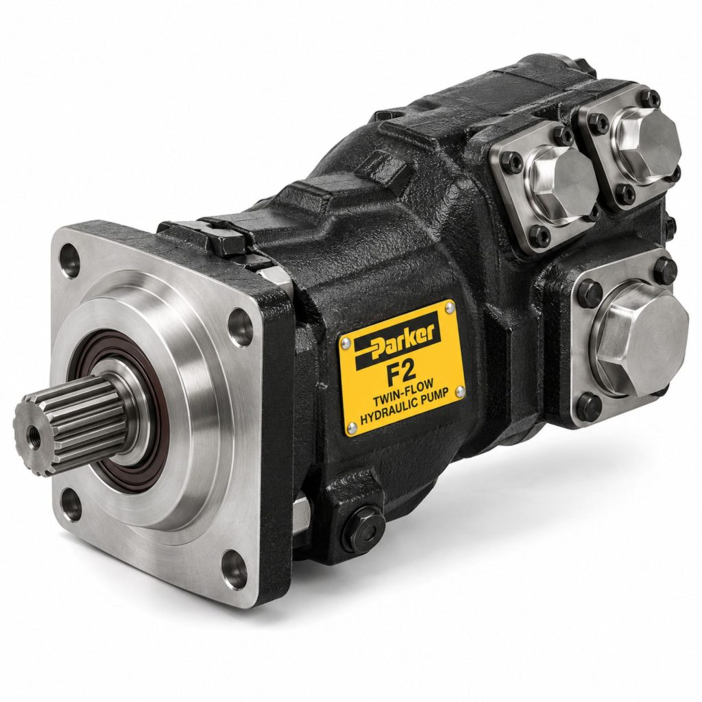
The Parker F2 is a twin-flow, fixed-displacement bent-axis axial-piston pump developed for commercial trucks and mobile hydraulic equipment requiring two hydraulic flows from a single PTO-driven pump.
The F2 is based on Parker’s established F1 truck-pump design but incorporates two separate pumping sections. Each section has its own pressure outlet, allowing one pump to supply two hydraulic circuits or two different functions.
Depending on the selected model, the two pumping sections may have equal or unequal displacements. Equal-displacement versions can supply similar flow to two circuits, while unequal versions can support functions with different flow requirements.
The F2 can also combine its two flows when the hydraulic circuit is designed for that purpose. This allows a system to use the outputs independently or direct their combined flow to a single function during selected operating conditions.
Key Characteristics
- Twin-flow hydraulic-pump design
- Two separate pressure outlets
- Single common input shaft
- Fixed displacement for each pumping section
- Bent-axis axial-piston construction
- Equal- and unequal-displacement configurations
- Operating pressure up to 400 bar
- Operating speed up to approximately 2,100 rpm
- High overall hydraulic efficiency
- Compact alternative to installing two separate pumps
- Supports simultaneous hydraulic functions
- Flows can be used independently or combined in suitable circuits
- Designed for direct mounting to compatible PTOs
- Developed for demanding truck-hydraulic applications
Major Components
- Pump housing
- Common input shaft
- Input-shaft bearings
- First piston rotating group
- Second piston rotating group
- Axial pistons
- Cylinder barrels
- Bent-axis drive arrangement
- Port plates
- Common suction inlet
- First pressure outlet
- Second pressure outlet
- Shaft seal
- Housing seals
- PTO mounting flange
- Internal lubrication passages
Product Type and Construction
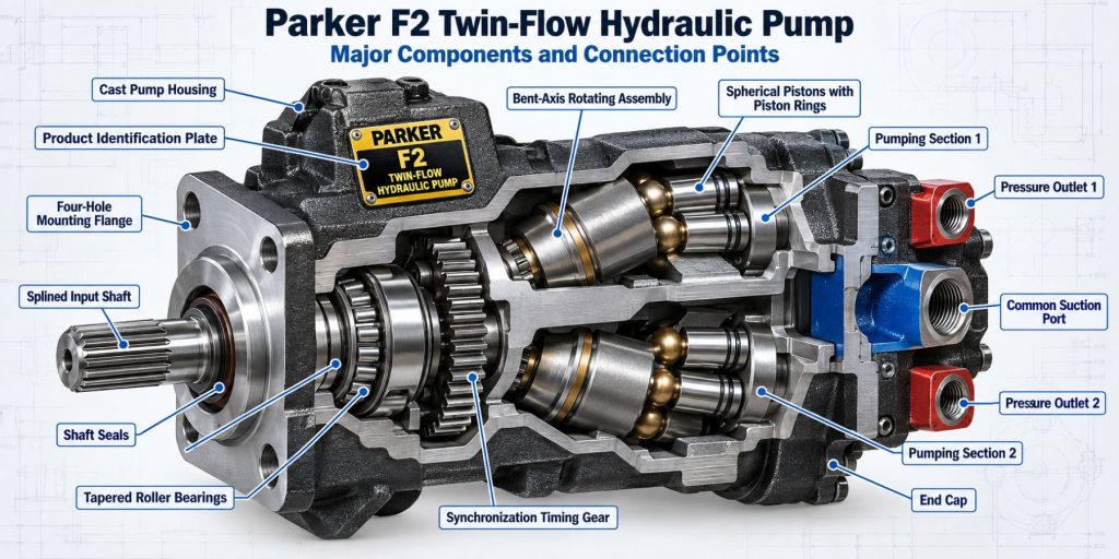
The F2 is a positive-displacement piston pump containing two fixed-displacement pumping sections driven by a common input shaft. The pump uses bent-axis geometry to create the piston movement needed to draw in and discharge hydraulic fluid.
Each pumping section delivers its own flow through a separate pressure port. Both sections normally draw hydraulic fluid through a common inlet arrangement connected to the reservoir.
This construction gives equipment designers two hydraulic outputs without requiring a tandem arrangement of two completely separate pumps. It can reduce installation length, mounting complexity, and the number of PTO outputs required.
How the Hydraulic Pump Works
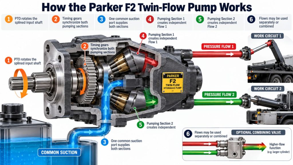
A compatible PTO rotates the F2 input shaft. The common shaft drives both bent-axis piston sections at the same speed.
As the rotating groups turn, their pistons move through intake and discharge strokes. Fluid enters through the suction circuit and is delivered through two separate pressure outlets.
The amount of flow produced by each outlet depends on that section’s displacement and the pump’s shaft speed. An equal-displacement pump produces approximately equal theoretical flow from both outlets, while an unequal-displacement model produces different flow from each section.
External valves determine whether the two flows operate separate functions, run simultaneously, or combine for a function requiring greater total flow.
Position and Function Within the Vehicle
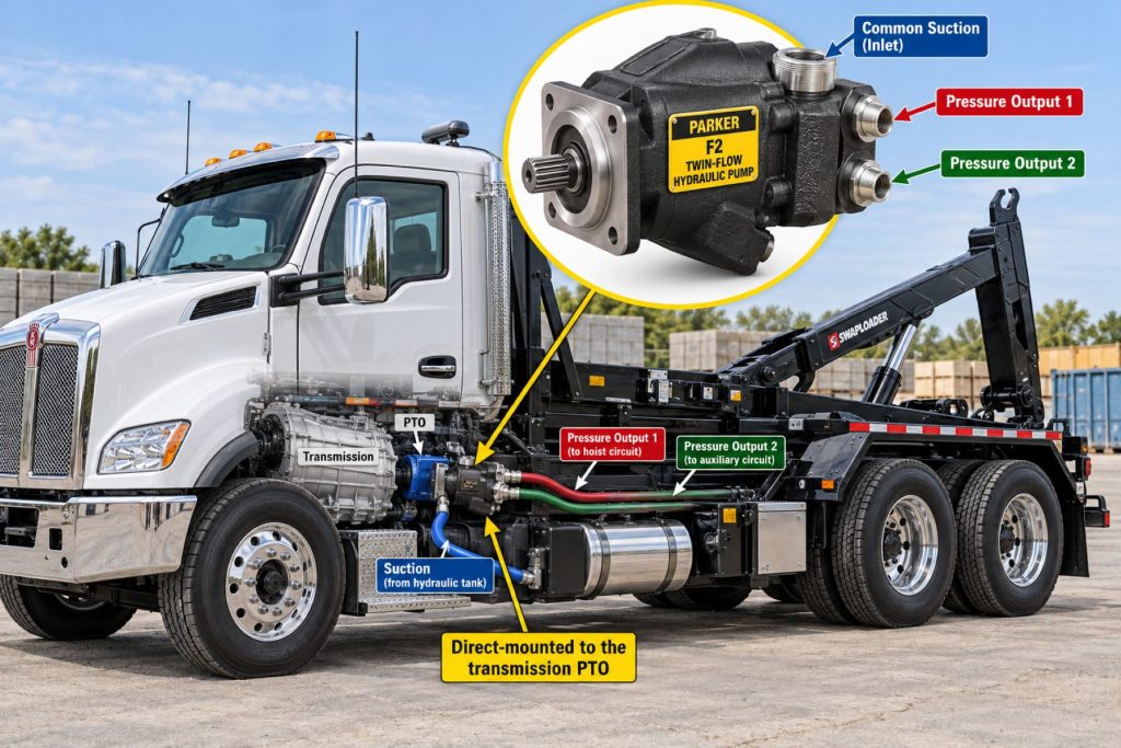
The Parker F2 normally mounts directly to a compatible transmission PTO. Its compact twin-flow construction allows two hydraulic circuits to be powered from one location beside or beneath the transmission.
The pump converts PTO-supplied rotary power into hydraulic flow for equipment such as cranes, compactors, mixer drums, spreaders, plows, loaders, stabilizers, conveyors, and hydraulic steering or accessory circuits.
The installation must provide clearance from the frame, driveshaft, exhaust system, suspension, fuel tanks, air tanks, and body equipment throughout normal powertrain and chassis movement.
Common Specifications
- Pump design: Twin-flow fixed-displacement bent-axis axial-piston pump.
- Number of pumping sections: Two.
- Number of pressure outlets: Two separate outlets.
- Displacement arrangement: Equal or unequal displacement, depending on model.
- Maximum published displacement: Up to approximately 68 cubic centimeters per revolution for each section in current United States product information.
- Maximum operating pressure: 400 bar or approximately 5,800 psi.
- Maximum operating speed: Up to approximately 2,100 rpm, depending on model and operating conditions.
- Hydraulic circuit: Open-circuit mobile hydraulic system.
- Mounting: Direct mounting to a compatible power take-off.
- Rotation: Application-specific right-hand or left-hand configuration.
- Flow use: Independent, simultaneous, or combined through an appropriately designed external hydraulic circuit.
Exact displacement combinations, flow ratings, torque requirements, speed limits, port arrangements, dimensions, and weights must be confirmed using the data for the selected Parker F2 model.
Displacement, Flow, Pressure, and Operating Capacity
Each F2 pumping section has a fixed displacement. The theoretical flow from each section is calculated from its displacement and shaft speed.
An equal-displacement configuration supplies similar flow through both pressure outlets. An unequal-displacement configuration can supply a higher-flow primary circuit and a lower-flow secondary circuit.
When the circuit combines the two flows, total output equals approximately the sum of the two section flows after normal efficiency losses. Both sections and every downstream component must remain within their approved pressure and flow limits.
The pump can support operating pressures up to 400 bar in approved applications. High pressure on both sections at the same time can require substantial input torque and horsepower from the PTO and transmission.
Twin-Flow Circuit Design
The defining feature of the F2 is its ability to provide two hydraulic flows through separate pressure outlets. This supports several circuit arrangements.
- Two independent hydraulic functions
- Two simultaneous functions operating at different pressures
- Primary and secondary equipment circuits
- Combined flow for faster equipment movement
- One high-flow circuit and one lower-flow circuit
- Separate circuits for working equipment and accessory functions
Check valves, unloading valves, directional valves, flow combiners, pressure-relief valves, and control logic may be required to manage the two outputs safely.
The two pressure ports should never be connected together without a circuit specifically designed to combine the flows. Pressure differences between the sections can create damaging reverse flow or excessive loading.
Independent and Combined Flow Operation
During independent operation, each pumping section supplies its own control valve or hydraulic function. One outlet may operate a crane boom while the other powers an accessory, stabilizer, steering, conveyor, or other circuit.
In a combined-flow arrangement, external valves direct both outputs toward one compatible function. Combining flow can increase actuator speed, but it also increases total power demand and the volume of fluid returning to the reservoir.
The circuit must prevent one section from forcing oil backward through the other. Proper check valves, unloading arrangements, pressure controls, and return plumbing are essential.
Intended PTO and Mounting Position
The F2 is designed for direct mounting to a PTO with a compatible pump flange, shaft, rotation, torque capacity, horsepower rating, and operating-speed range.
Because the pump can place both sections under load simultaneously, PTO selection must consider the combined input-torque requirement rather than evaluating each outlet separately.
The selected PTO ratio should provide the required flow at a practical engine speed without exceeding the F2’s maximum speed or the allowable power of the PTO and transmission.
Bent-Axis Piston Design
The F2 uses two bent-axis piston groups driven by a common shaft. The angled relationship between each cylinder barrel and the drive shaft creates the reciprocating piston motion that moves hydraulic fluid.
This design supports high pressure, strong hydraulic efficiency, and substantial power density. It allows two pumping sections to be packaged more compactly than many separate-pump installations.
The precision piston groups depend on clean hydraulic fluid and adequate inlet conditions. Contamination, aeration, cavitation, or dry operation can damage the rotating groups and port surfaces.
PTO Speed and Pump Rotation
The F2’s direction of rotation must match the PTO output. Rotation should be confirmed using Parker’s specified viewing direction and the full pump model information.
Pump speed is determined by engine rpm, the transmission’s PTO-drive gearing, and the PTO’s internal ratio. Both F2 sections rotate at the same speed because they share a common input shaft.
Increasing pump speed increases flow from both outlets. Engine-speed control should therefore account for the flow limits of both hydraulic circuits, not only the function currently carrying the highest load.
Hydraulic Circuit and Equipment Integration
A complete F2 hydraulic system may include:
- Hydraulic reservoir
- Common suction plumbing
- Two pressure hoses
- Separate pressure-relief valves
- Check valves
- Flow-combining or unloading valves
- Directional-control valves
- Return hoses
- Return and pressure filtration
- Hydraulic cylinders or motors
- Oil cooler
- Pressure and temperature sensors
- Electronic or pneumatic equipment controls
Each circuit must be sized for its expected pressure and flow. The reservoir and return system must also handle the maximum combined flow when both sections operate simultaneously.
Inlet, Outlet, and Port Design
The F2 normally uses a common inlet to supply both pumping sections. The suction hose and reservoir connection must provide enough oil for the combined maximum inlet demand.
An inlet system that would be adequate for a single-flow pump may be too restrictive for the F2. Hose diameter, length, fittings, fluid viscosity, reservoir position, and pump speed must all be considered.
The two pressure outlets may operate at different pressures when the system is properly designed. Each outlet requires correctly rated hoses, fittings, valves, relief protection, and monitoring.
Controls and Electronic Integration
The Parker F2 is mechanically driven and does not normally use electronic displacement control. Both fixed-displacement sections begin producing flow when the PTO engages and rotates the pump.
External controls can manage how the two flows are used. These may include:
- PTO engagement switch
- Engine-speed control
- Electric-over-hydraulic directional valves
- Flow-combining valves
- Unloading valves
- Pressure switches and transducers
- Temperature sensors
- Equipment-control modules
- Remote-control systems
- Safety and body-equipment interlocks
The control system should prevent unsafe pressure combinations, uncontrolled actuator movement, excessive pump speed, and operation with an inadequate fluid supply.
Efficiency, Heat, and Lubrication
The F2’s bent-axis piston construction provides high overall efficiency, helping convert PTO power into hydraulic output with limited internal loss.
Operating both sections at high pressure can produce substantial heat even when pump efficiency is high. Pressure losses in hoses, valves, flow combiners, and return circuits add to the total heat load.
Hydraulic fluid lubricates both pumping sections. Clean fluid of the correct viscosity must reach the pump immediately after startup.
Reservoir capacity and oil-cooler selection should account for the total output of both sections and the longest expected operating cycle.
Duty Cycle and Operating Conditions
The F2’s allowable operating load depends on displacement, pump speed, pressure at each outlet, total input power, oil temperature, inlet condition, and cycle duration.
One section may operate at high pressure while the second operates at lower pressure. The combined torque demand must still remain within the pump, PTO, transmission, and engine limits.
Cold hydraulic fluid can restrict the common inlet and increase the risk of cavitation. The system should be warmed at reduced speed and pressure before both circuits are placed under heavy load.
Applications with continuous high flow or frequent combined-flow operation may require a larger reservoir, more efficient plumbing, and an oil cooler.
Mounting and Installation
The F2 must be matched to the PTO output, rotation, mounting flange, shaft, speed, torque, and chassis installation. Parker’s instructions for the exact pump model should be followed.
The installer should verify:
- Correct displacement combination
- Correct pump rotation
- Compatible PTO flange and shaft
- Adequate PTO torque and horsepower
- Maximum permitted pump speed
- Combined inlet-flow requirement
- Correct identification of both pressure ports
- Separate relief protection for each circuit
- Reservoir and return-flow capacity
- Pump and chassis clearance
- Pump-support requirements
- Hydraulic-fluid specification
- Filtration and cooling requirements
- Correct priming before initial startup
The pump should never be started dry. Both sections and the common inlet circuit must be filled and vented according to the installation procedure.
PTO and Vehicle Compatibility
The Parker F2 can be paired with a compatible Parker Chelsea, Muncie, or other approved PTO when the mechanical connection and performance ratings match.
The PTO must support the combined torque and horsepower required by both pumping sections. A PTO suitable for one equivalent single-flow circuit may be undersized when both F2 outlets operate under load.
Vehicle compatibility also depends on transmission PTO provisions, engine speed, frame clearance, driveshaft location, exhaust routing, chassis movement, body equipment, and hydraulic-reservoir placement.
Hydraulic Fluid, Filtration, and Reservoir Compatibility
The hydraulic fluid must provide the viscosity, lubrication, anti-wear protection, oxidation resistance, and temperature performance required by Parker and the other system components.
The reservoir and suction plumbing must supply both pumping sections without excessive vacuum or turbulence. The usable oil volume should support the combined flow and allow time for cooling, air separation, and contamination settlement.
Filtration should maintain the required cleanliness without starving the inlet or restricting the combined return flow. Separate return filters or a larger common return filter may be required.
Return lines should enter the reservoir in a way that limits foaming and prevents aerated oil from being drawn directly back into the common pump inlet.
Common Applications
- Truck-mounted cranes
- Forestry cranes
- Refuse trucks
- Concrete mixers
- Hooklift trucks
- Roll-off trucks
- Skip loaders
- Snowplows and material spreaders
- Municipal maintenance trucks
- Utility trucks
- Recovery vehicles
- Hydraulic stabilizer systems
- Conveyor and compactor systems
- Multipurpose vocational vehicles
- Equipment requiring simultaneous hydraulic functions
Advantages
- Two hydraulic flows from one pump
- Two separate pressure outlets
- Equal- and unequal-displacement options
- Supports simultaneous hydraulic functions
- Flows can be combined in properly designed systems
- Operating pressure up to 400 bar
- High overall hydraulic efficiency
- Compact alternative to two separate pumps
- Single PTO connection
- Bent-axis piston construction
- Designed for demanding truck applications
- Can simplify multifunction hydraulic-system packaging
- Current Parker technical and distributor support
Limitations or Considerations
- More complex hydraulic circuit than a single-flow pump
- Both sections rotate whenever the PTO drives the pump
- Combined power demand can be substantial
- Common inlet must supply both pumping sections
- Each pressure circuit requires proper relief protection
- Incorrectly combining outlets can damage the pump or system
- Fixed displacement cannot automatically adjust to flow demand
- Maximum flow changes directly with shaft speed
- Requires clean hydraulic fluid
- Sensitive to suction restriction and aeration
- Direct-mounted installation may require additional support
- Reservoir and return plumbing must handle combined flow
- Incorrect rotation can cause immediate damage
- System design requires careful hydraulic engineering
Driver and Operator Experience
The operator normally activates the F2 by engaging the vehicle’s PTO. Once engaged, both pumping sections rotate and make flow available to their respective circuits.
The equipment controls determine which hydraulic functions operate and whether the flows remain separate or are combined. Operators may be able to use two functions simultaneously when the system is designed for multifunction operation.
Slow response, jerking, excessive noise, overheated fluid, reduced lifting capacity, or interaction between functions may indicate a problem with the pump, valves, plumbing, reservoir, or control strategy.
PTO Engagement and Hydraulic Operating Procedure
The exact operating procedure depends on the vehicle and equipment. A general sequence may include:
- Position and secure the vehicle as required.
- Inspect both hydraulic circuits for leaks or damage.
- Confirm the hydraulic-fluid level.
- Place the vehicle and transmission in the approved PTO mode.
- Reduce engine speed to the approved engagement range.
- Engage the PTO.
- Allow the hydraulic system to warm at reduced pressure when necessary.
- Operate the required hydraulic function or functions.
- Use combined-flow mode only when permitted by the equipment design.
- Monitor pressure, temperature, noise, and equipment movement.
- Return the controls to their approved neutral positions.
- Reduce engine speed and disengage the PTO.
This operating overview does not replace instructions from Parker, the PTO manufacturer, the vehicle builder, or the equipment manufacturer.
Inspection and Wear Points
- Pump housing
- Input shaft and spline
- PTO mounting flange
- Pump-support bracket
- Shaft seal
- Common suction hose
- Suction fittings and clamps
- First pressure outlet and hose
- Second pressure outlet and hose
- Pressure-relief valves
- Check valves and flow combiner
- Return hoses and filters
- Reservoir level and condition
- Hydraulic-fluid cleanliness
- Operating temperature
- Abnormal noise or vibration
Lubrication Requirements
The hydraulic fluid lubricates both F2 pumping sections. The pump must receive clean oil of the correct type and viscosity immediately after startup.
The pump and suction circuit should be filled and vented according to Parker’s installation instructions. Starting the pump dry can damage both piston rotating groups.
The hydraulic-fluid level must remain sufficient during every equipment position and operating condition. Fluid should be replaced according to its condition and the maintenance requirements of the complete hydraulic system.
Maintenance and Ownership Notes
Inspect the F2 for hydraulic leaks, loose fasteners, damaged plumbing, excessive heat, unusual noise, and changes in equipment performance.
Because both sections share a common inlet, suction-side maintenance is especially important. A restricted inlet can affect both hydraulic circuits at the same time.
Pressure-relief, check, unloading, and flow-combining valves should be tested periodically. A control-valve problem can create pressure interaction between the two pump sections.
Following a pump failure, both circuits should be inspected and cleaned as necessary. Contamination can travel through either pressure outlet and return to the common reservoir.
Common Pump and Hydraulic-System Problems
- Neither circuit produces flow: A disengaged PTO, broken input connection, incorrect rotation, empty reservoir, blocked common inlet, trapped air, or internal pump failure may stop both outputs.
- Only one circuit produces flow: Internal damage to one pumping section, a blocked pressure line, failed control valve, stuck check valve, or incorrect plumbing may affect one outlet.
- Cavitation noise: An undersized common inlet, cold oil, low reservoir level, clogged breather, collapsed hose, excessive pump speed, or restricted fitting may starve both sections.
- Uneven circuit performance: Different section displacements, pressure settings, valve restrictions, hose sizes, actuator loads, or internal wear may cause different operating speeds.
- One function affects another: Incorrect check-valve placement, improper flow combining, shared return restriction, control-valve leakage, or inadequate reservoir plumbing may allow circuit interaction.
- Hydraulic system overheats: Combined high-pressure operation, continuous relief flow, undersized plumbing, an inadequate reservoir, valve losses, or insufficient cooling may generate excessive heat.
- Shaft-seal leakage: Seal wear, contamination, excess case pressure, misalignment, unsupported pump weight, or excessive temperature may cause leakage.
- PTO overload: High pressure on both sections, an oversized displacement combination, excessive pump speed, pressure spikes, or a seized component can overload the PTO.
Safety and Service Precautions
Never install or service the F2 with the engine running. Disengage the PTO, remove the ignition key, secure the vehicle, and chock the wheels.
Both pressure circuits must be depressurized before hoses, valves, fittings, or pump components are disconnected. Releasing pressure from one circuit does not necessarily depressurize the other.
Raised bodies, cranes, stabilizers, booms, and other hydraulic equipment must be mechanically blocked before service. Hydraulic pressure must never be trusted to support raised equipment.
Never use bare hands to locate a hydraulic leak. High-pressure fluid can penetrate skin and requires immediate emergency medical treatment.
Identification Information
The pump identification label should be used to confirm its complete model, displacement combination, rotation, ports, and production information.
- Parker F2 series designation
- Complete model number
- Parker part number
- First-section displacement
- Second-section displacement
- Direction of rotation
- Maximum operating pressure
- Maximum permitted speed
- Mounting-flange specification
- Input-shaft specification
- Suction-port information
- First and second pressure-port identification
- PTO manufacturer and model
- Vehicle and equipment application
F2 pumps with similar housings may have different displacement combinations and rotation. Replacement pumps should be selected using the full identification information.
Buying Considerations
- Determine the required flow for each hydraulic circuit.
- Confirm the maximum pressure of each circuit.
- Choose an equal- or unequal-displacement configuration.
- Calculate total pump torque and horsepower demand.
- Confirm the PTO’s continuous and intermittent ratings.
- Calculate pump speed from engine speed and PTO ratio.
- Confirm the correct direction of rotation.
- Match the PTO flange and shaft.
- Determine whether the flows will operate independently or combine.
- Size the common suction plumbing for total flow.
- Provide relief protection for both circuits.
- Size the reservoir and return system for combined flow.
- Review filtration and oil-cooling requirements.
- Check chassis clearance and pump support.
- Use an installer experienced with twin-flow hydraulic systems.
Variants and Configurations
- Equal-displacement twin-flow pumps
- Unequal-displacement twin-flow pumps
- Different total displacement capacities
- Right-hand rotation
- Left-hand rotation
- Independent-circuit installations
- Simultaneous-function installations
- Combined-flow installations
- Direct PTO-mounted configurations
- Application-specific port and fitting arrangements
- Truck-crane hydraulic systems
- Refuse and mixer hydraulic systems
- Snow and ice control systems
- Multipurpose municipal-vehicle systems
Comparison to Similar Equipment
Compared with the Parker F1 Hydraulic Pump, the F2 provides two separate hydraulic outputs. The F1 supplies one fixed-displacement flow and may be simpler for equipment requiring only one main hydraulic circuit.
Compared with the future Parker F4 Twin-Flow Hydraulic Pump, the F2 represents Parker’s established twin-flow truck-pump design. The F4 uses a newer application-specific design and must be compared by displacement, speed, mounting, and circuit requirements.
Compared with the future Parker VP1 Variable-Displacement Hydraulic Pump, the F2 delivers two fixed displacements. The VP1 adjusts displacement according to system demand in a compatible load-sensing circuit.
Compared with installing two separate hydraulic pumps, the F2 can reduce installation length and use one PTO connection. Separate pumps may offer greater flexibility in placement, independent speed, or completely isolated hydraulic systems.
Best Fit For
- Trucks requiring two hydraulic flows
- Equipment operating simultaneous hydraulic functions
- Systems requiring different flow rates for separate functions
- Applications that periodically combine two flows
- Truck-mounted cranes
- Forestry cranes
- Refuse trucks
- Concrete mixers
- Hooklift and roll-off trucks
- Snow and ice control equipment
- Multipurpose municipal vehicles
- Installations where two separate pumps would use excessive space
- Vehicles with a PTO rated for the combined pump load
Related Vehicle and Trailer Types
- Complete Guide to Semi Truck Types
- Class 6 vs Class 7 vs Class 8 Trucks
- Crane Trucks
- Refuse Trucks
- Concrete Mixer Trucks
- Hooklift Trucks
- Roll-Off Trucks
- Logging Trucks
- Utility Trucks
- Snowplow Trucks
Related Truck and Trailer Models
- Freightliner 114SD
- Freightliner 122SD
- International HX Series
- Kenworth T880
- Peterbilt 567
- Mack Granite
- Volvo VHD
- Western Star 47X
- Western Star 49X
Related PTO and Hydraulic System Types
- Hydraulic Pumps & Motors
- Power Take-Off Systems
- Wet Kits & Complete Hydraulic Systems
- Hydraulic Cylinders & Dump Hoists
- Hydraulic Valves, Controls & Reservoirs
- Hydraulic Hoses, Fittings & Filtration
Related PTO and Hydraulic Products
- Parker F1 Hydraulic Pump
- Parker F4 Twin-Flow Hydraulic Pump
- Parker VP1 Variable-Displacement Hydraulic Pump
- Muncie E Series Hydraulic Pump
- Permco P5151 Hydraulic Pump
- Bezares BEZA Lightweight Hydraulic Pump
- Parker Chelsea Wetline Hydraulic System
- Parker Chelsea 590 Series Power Take-Off
- Parker Chelsea 870 Series Power Take-Off
- Muncie WETLINE Hydraulic System
Related Equipment Systems
- PTO & Hydraulic Systems
- Transmissions
- Electrical Systems
- Axles & Differentials
- Suspension Systems
- Brake Systems
Related Guides
- PTO & Hydraulic System Guides
- How Commercial Truck PTO and Hydraulic Systems Work
- Commercial Truck Power Take-Off Types Explained
- How to Choose a PTO and Hydraulic Pump
- Commercial Truck Wet Kits Explained
- How to Inspect and Maintain Truck Hydraulic Systems
Regulatory and Compliance Notes
The F2 and its hydraulic circuits must comply with applicable vehicle, workplace-safety, hydraulic-equipment, guarding, hose-routing, and final-stage manufacturing requirements.
Every pressure-containing component must be rated for the maximum pressure and flow of its circuit. Separate pressure outlets must receive appropriate overpressure protection.
The installation must not interfere with steering, braking, driveline, exhaust, emissions, fuel, electrical, or stability systems. Added equipment must remain within the vehicle’s axle and gross weight ratings.
Real World Operating Notes
The primary advantage of the F2 is not simply greater total flow. Its greatest value is the ability to supply two hydraulic demands from one compact PTO-driven pump.
The common suction circuit must be sized for both sections operating together. Suction plumbing based on only one outlet’s flow can cause cavitation and damage both piston groups.
If one function slows whenever the second function operates, the problem may involve engine speed, PTO capacity, inlet restriction, reservoir design, control-valve priority, or total available power rather than pump wear.
After a major internal failure, both pressure circuits, the common reservoir, cooler, filters, and return system should be cleaned and inspected before a replacement pump is installed.
Frequently Asked Questions
What is the Parker F2 Twin-Flow Hydraulic Pump?
The F2 is a PTO-driven fixed-displacement bent-axis piston pump that supplies two separate hydraulic flows from one pump assembly.
Does the F2 contain two pumps?
It contains two pumping sections driven by one common input shaft and packaged within a single pump assembly.
Can both F2 outputs operate at the same time?
Yes. Both sections can support simultaneous functions when the PTO, engine, reservoir, plumbing, valves, and equipment are designed for the combined demand.
Can the two F2 flows be combined?
Yes, but only through a correctly engineered circuit using the appropriate check, unloading, combining, and pressure-control valves.
Do both F2 sections have the same displacement?
Not always. Depending on the selected model, the two sections may have equal or unequal displacements.
What pressure can the F2 operate at?
The series has published operating-pressure capability up to 400 bar, or approximately 5,800 psi, in properly engineered applications.
Does each outlet need a pressure-relief valve?
Each circuit requires appropriate overpressure protection. The exact valve arrangement depends on whether the outputs operate separately or are combined.
Can the F2 replace two separate pumps?
In many suitable applications it can provide the two required flows from one PTO connection. System pressure, flow, isolation, packaging, and control requirements must still be evaluated.
What causes both F2 circuits to become noisy?
A low fluid level, restricted common inlet, cold oil, excessive speed, aeration, clogged reservoir breather, or collapsed suction hose may affect both sections.
How is the correct replacement F2 identified?
Use the complete Parker part and model number, both displacement values, rotation, shaft, mounting flange, port arrangement, and application information.
Availability and Where to Find
Parker F2 pumps, hydraulic valves, hoses, fittings, filters, reservoirs, and compatible Parker Chelsea PTOs may be available through Parker distributors, commercial-truck equipment dealers, body builders, hydraulic specialists, and vocational-equipment installers.
Availability depends on displacement combination, rotation, input shaft, mounting flange, port arrangement, pressure requirements, and regional product configuration.
Current technical information, product options, literature, and distributor resources are available through Parker’s F2 Series hydraulic-pump page.
Support Trucking Families
Truck Equipment Atlas supports the mission of Grey Cross, a nonprofit dedicated to helping families of truck drivers who lose their lives while on the road. As the site grows, part of its mission is to bring awareness and support to these families.
Podcast or Video Section
Learn More Through Audio and Video
Truck Equipment Atlas will continue expanding with podcast episodes, interviews, and equipment breakdowns to help drivers and fleets better understand trucks and equipment.
Follow the Growth of Truck Equipment Atlas
Truck Equipment Atlas continues to expand with new truck profiles, trailer coverage, diesel engine pages, equipment system resources, manufacturer information, and educational guides.
Visit our Site Updates page to explore recent additions, project milestones, and upcoming resources as we continue building one of the industry’s growing commercial trucking equipment reference libraries.
View the Latest Site Updates: Truck Equipment Atlas Site Updates