
Quick Facts
- Manufacturer: Permco
- Product Series: DM Series
- Model: DM-640-25
- Product Type: Remote-mount hydraulic dump pump and control-valve assembly
- Pump Design: External gear pump with an integrated directional-control valve
- Primary Application: Medium- and heavy-duty dump trucks and dump trailers
- Rated Flow: Approximately 46 GPM at 1,800 rpm
- Maximum Pressure: Up to 2,500 psi when properly configured
- Maximum Pump Speed: Up to 2,400 rpm
- Hydraulic Circuit Options: Two-line or three-line
- Shift Options: Manual or air-operated configurations
- Mounting Type: Remote mount with separate driveshaft and mounting bracket
- Production Status: Confirm exact configuration and availability with Permco or an authorized distributor
Overview
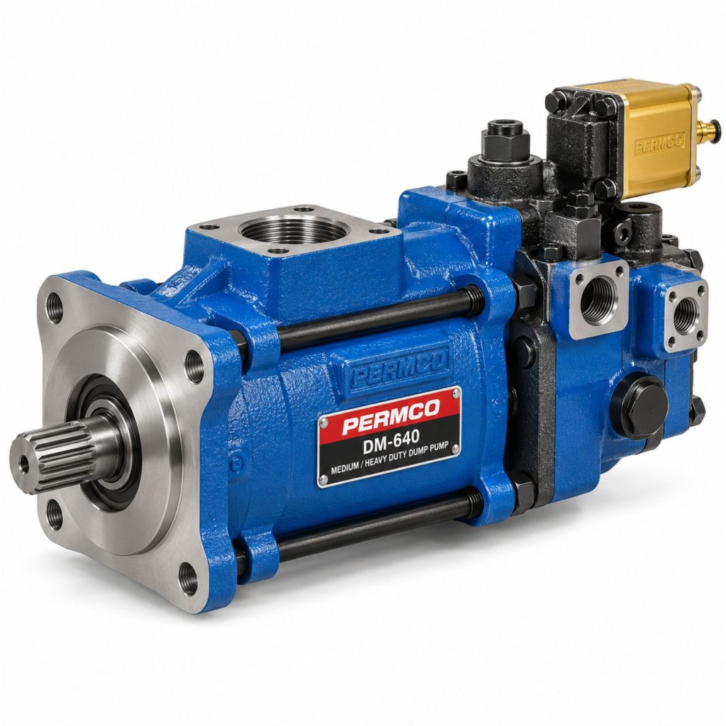
The Permco DM-640 is a remote-mount hydraulic dump pump designed for medium- and heavy-duty dump trucks and dump trailers. It combines a high-output external gear pump with a directional-control valve, load check, and pressure-relief valve in one assembly.
The DM-640-25 uses a 2.5-inch gear set and is rated to produce approximately 46 gallons per minute at 1,800 pump rpm. Its higher flow makes it suitable for large dump bodies and hydraulic cylinders that require faster extension than a lower-output dump pump can provide.
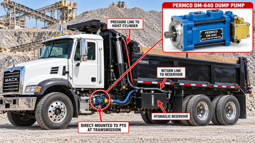
Unlike a direct-mount dump pump attached directly to a compatible PTO output, the DM-640 is remotely mounted to the truck chassis and driven through a short hydraulic-pump driveshaft. This arrangement can provide additional flexibility when PTO location, transmission clearance, chassis equipment, or pump-access requirements prevent direct mounting.
The pump can be configured for a two-line intermittent-duty hydraulic circuit or a three-line circuit that returns neutral and cylinder-retraction flow directly to the reservoir. Correct circuit selection, PTO speed, driveshaft alignment, reservoir capacity, hose sizing, and operating procedure are essential for reliable service.
Key Characteristics
- Remote-mount dump-pump design
- External gear pumping section
- Integrated raise, neutral, and lower control valve
- Approximately 46 GPM at 1,800 rpm
- Maximum operating pressure up to 2,500 psi
- Maximum speed up to 2,400 rpm
- Two-line and three-line circuit compatibility
- Built-in load check helps maintain dump-body position
- Factory-set direct-acting pressure-relief valve
- Manual and air-shift configurations
- Pressure-balanced wear plates
- High-strength alloy-steel gears and shafts
- Designed for medium- and heavy-duty dump applications
Major Components
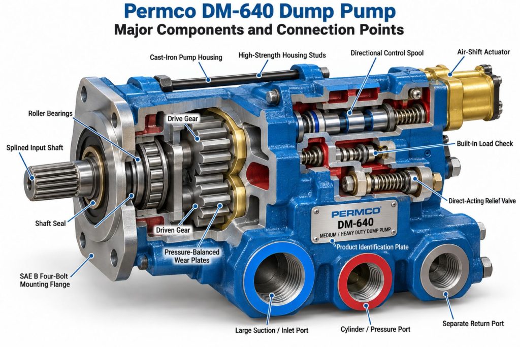
- External gear pump
- Gear housing
- Twin input and output shaft arrangement
- Roller bearings
- Pressure-balanced thrust plates
- Shaft seals
- Integrated directional-control valve
- Raise, neutral, and lower spool
- Spool detent components
- Built-in load-check valve
- Direct-acting pressure-relief valve
- Cylinder pressure port
- Reservoir inlet port
- Three-line return port
- Remote-mount bracket
- Manual shift linkage or air-shift actuator
- Identification plate
Product Type and Construction
The DM-640 is an integrated pump-and-valve assembly rather than a general-purpose hydraulic pump. Its external gear section creates hydraulic flow, while the attached valve housing directs that flow to raise or lower a single-acting telescopic dump cylinder.
The pump uses high-strength alloy-steel gears and shafts supported by roller bearings. Pressure-balanced wear plates help maintain operating efficiency as pressure changes and the pump accumulates service hours.
The remote-mount arrangement uses a keyed shaft and mounting bracket. A short driveline connects the pump to a properly selected transmission-mounted PTO. The driveline, pump, and PTO must be aligned and guarded according to the manufacturers’ instructions.
How the Dump Pump Works
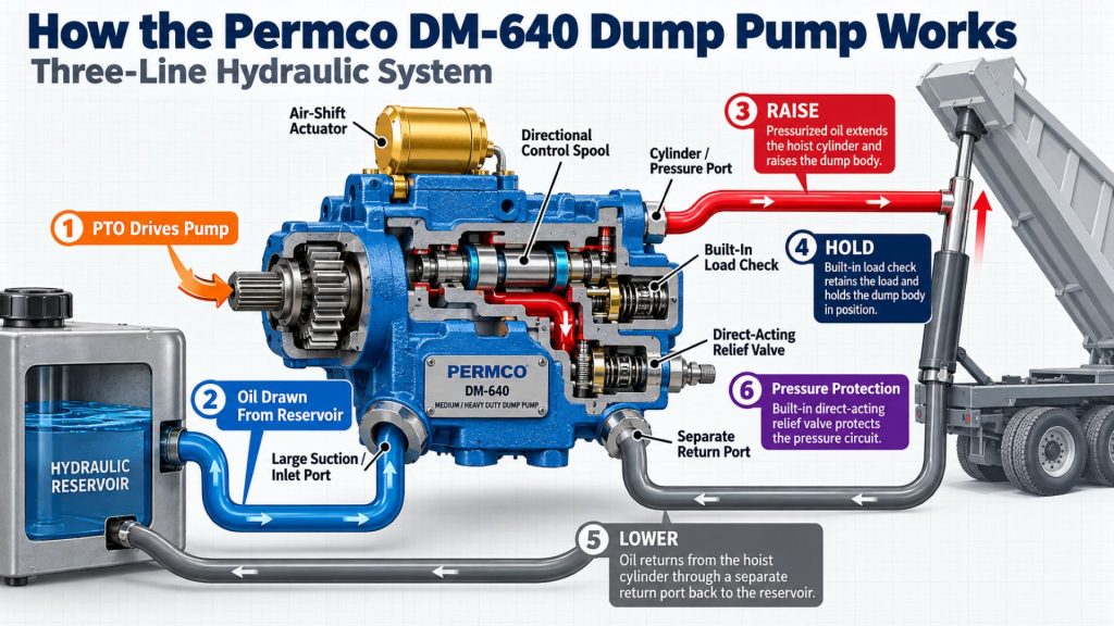
When the transmission PTO is engaged, the PTO rotates the pump through the remote driveshaft. The pump draws hydraulic fluid from the reservoir and moves it through the integrated control valve.
With the valve placed in the raise position, pressurized oil flows through the cylinder port to the dump cylinder. The cylinder extends and raises the dump body or trailer body. The built-in load check helps prevent oil from flowing backward and assists in holding the body at the selected angle.
In neutral, the route taken by the oil depends on whether the system uses a two-line or three-line circuit. A two-line system recirculates oil internally through the pump assembly. A correctly configured three-line system directs the neutral flow through a separate return hose to the reservoir.
When the valve is moved to lower, fluid leaving the cylinder returns through the valve. Gravity normally retracts the single-acting cylinder as the dump body descends. The control spool allows the operator to meter the lowering speed within the limits of the installed system.
Position and Function Within the Vehicle
The DM-640 is normally installed on the truck frame near the transmission and PTO. It must be positioned so that the pump driveshaft remains short, correctly aligned, and protected from contact with the frame, exhaust system, suspension, driveline, and road debris.
Within the hydraulic system, the pump performs three primary functions: generating hydraulic flow, controlling cylinder movement, and limiting excessive pressure through its relief valve. The reservoir supplies hydraulic fluid, while hoses connect the pump to the tank and dump cylinder.
Common Specifications
- Pump Configuration: Remote-mount external gear dump pump with integrated control valve
- Model Designation: DM-640-25
- Gear Width: 2.5 inches
- Nominal Flow: Approximately 46 GPM at 1,800 rpm
- Maximum Pressure: Up to 2,500 psi
- Maximum Speed: Up to 2,400 rpm
- Standard Shaft: One-inch keyed shaft on applicable remote-mount configurations
- Inlet Port: 1¼-inch NPT
- Cylinder Port: One-inch NPT
- Return Port: One-inch NPT for three-line installation
- Hydraulic Circuits: Two-line or three-line
- Valve Positions: Raise, neutral, and lower
- Shift Options: Manual cable control or air-shift configuration
- Relief Settings: Common configurations include 2,000- and 2,500-psi settings
- Valve Orientation: Application-specific left- or right-side arrangements
Specifications vary by complete Permco ordering code. Confirm the shaft, rotation, valve orientation, shift mechanism, circuit configuration, and relief setting before ordering or installing a replacement pump.
Displacement, Flow, Pressure, and Operating Capacity
The DM-640-25 uses a 2.5-inch gear set and produces approximately 46 GPM at 1,800 rpm under the published rating conditions. Actual flow at the cylinder is affected by pump speed, hydraulic pressure, fluid temperature, hose restriction, valve losses, internal leakage, and component condition.
Permco identifies pressure capability up to 2,500 psi and speed capability up to 2,400 rpm for the applicable assembly. These figures are component limits, not recommended continuous operating targets. The PTO ratio must keep pump speed within its allowable range at the engine speed used for dumping.
The relief valve protects the hydraulic circuit from excessive pressure, but it should not be used as a normal body-position stop. Prolonged operation over relief generates substantial heat and can damage the pump, hydraulic fluid, hoses, seals, cylinder, and reservoir system.
Two-Line and Three-Line Hydraulic Circuits
A two-line installation uses one suction line between the reservoir and pump and one pressure line between the pump and cylinder. When the PTO remains engaged with the control valve in neutral, oil recirculates internally and heats rapidly.
Permco reports a temperature increase of approximately 7.5°F per minute during two-line neutral operation and recommends limiting operation in this mode to five minutes. Excessive neutral operation can reduce internal clearances as components expand, potentially causing pump seizure or shaft failure.
A three-line system adds a dedicated return hose from the pump to the reservoir. The Permco RZ-0206 sleeve is installed in the inlet-valve passage so neutral, relief, and cylinder-retraction flow can return directly to the tank. Permco recommends limiting operation in the three-line mode to no more than ten minutes because heat generation is reduced but not eliminated.
The three-line sleeve must not be installed in a two-line circuit. Installing it without the required return hose can create a hazardous operating condition.
PTO Speed and Pump Rotation
The PTO ratio, transmission operating speed, and engine rpm determine DM-640 pump speed. Because the pump can produce approximately 46 GPM at 1,800 rpm, an incorrectly selected PTO can overspeed the pump or produce more cylinder flow than the body and hydraulic system can safely handle.
The pump’s required rotation must match the PTO output and driveshaft arrangement. Remote-mount DM-640 ordering codes may identify right- or left-oriented valve arrangements, but the complete model code and rotation markings should be verified rather than inferred from appearance alone.
A qualified PTO and hydraulic-equipment installer should calculate pump rpm at the intended engine speed before the truck enters service.
Hydraulic Circuit and Equipment Integration
The DM-640 must be integrated with a correctly sized reservoir, suction hose, cylinder hose, return hose when applicable, breather, filter arrangement, PTO, controls, and dump cylinder.
System design should account for:
- Required cylinder flow and extension time
- Maximum cylinder and hose pressure
- Dump-body weight and geometry
- PTO ratio and engine operating speed
- Reservoir volume and fluid cooling
- Suction-line velocity and restriction
- Return-line capacity
- Filter flow rating and bypass pressure
- Hydraulic-fluid viscosity and temperature range
- Body-prop and safety-control requirements
Ports, Hoses, and Return-Line Design
The published DM-640 arrangement uses a 1¼-inch NPT inlet, a one-inch NPT cylinder port, and a one-inch NPT return port. Hose inside diameter and fitting selection must preserve adequate flow rather than simply matching the threaded port size.
For conversion to three-line operation, Permco specifies a one-inch inside-diameter return hose from the pump. If a return filter is installed, Permco identifies a one-inch hose from the pump to the filter and a 1¼-inch hose from the filter to the reservoir. The filter arrangement must be capable of handling the system’s return flow without creating excessive backpressure.
The suction hose should be kept short, properly supported, free of internal collapse, and routed away from excessive heat. Restricted inlet flow can cause cavitation, noise, poor performance, and rapid pump damage.
Controls and Air-Shift Integration
Manual-shift DM-640 configurations can be operated through a properly adjusted cable and control lever. A neutral lockout safety cap may be used with pull-out cable controls to help prevent unintended spool movement.
Air-shift versions use an air actuator and cab-mounted controls to move the valve between raise, neutral, and lower positions. The air supply, control valve, tubing, fittings, and actuator must be installed according to the Permco instructions.
Air-shift controls do not replace the need for proper PTO controls, body-position awareness, and safe operating procedures. Operators must be able to positively identify the PTO and valve positions before moving the vehicle.
Efficiency, Heat, and Lubrication
Pressure-balanced wear plates help maintain pumping efficiency across the operating range. Even so, all hydraulic pumps convert some input power into heat through internal leakage, fluid friction, valve pressure drop, and hose restriction.
Heat generation becomes especially important when the PTO remains engaged in neutral or when the pump operates against the relief valve. Three-line plumbing provides a lower-restriction return path, but it does not make the DM-640 suitable for unlimited continuous operation.
The hydraulic fluid lubricates the pump’s internal components. Clean fluid of the correct viscosity, an unrestricted suction supply, and proper reservoir ventilation are necessary for lubrication and cooling.
Duty Cycle and Operating Conditions
The DM-640 is designed around dump-body raise-and-lower cycles. It should not be treated as a general continuous-duty hydraulic power source.
Permco does not recommend this dump-pump design for ejector bodies, conveyor systems, or moving-floor trailers. Those applications normally require a hydraulic system designed for longer operating periods and different flow-control demands.
Operating conditions that influence pump life include ambient temperature, fluid cleanliness, engine speed, PTO ratio, load, cycle frequency, reservoir size, hose routing, and time spent in neutral or over relief.
Mounting and Installation
The remote-mount pump should be secured to a properly engineered chassis bracket. The mount must support the pump without allowing movement, vibration, or frame interference.
The PTO-to-pump driveshaft must have correct alignment, working angles, slip travel, phasing, fastener retention, and guarding. Excessive misalignment can damage the pump bearings and shafts while creating a serious rotating-equipment hazard.
During initial startup, Permco instructs technicians to prime the pump with the spool in the raise position. It may be necessary to loosen an appropriate fitting carefully to bleed trapped air according to the manufacturer’s service procedure.
PTO and Vehicle Compatibility
Compatibility depends on the truck, transmission, PTO opening, PTO model, PTO ratio, engine operating speed, available frame space, hydraulic-cylinder requirements, and dump-body design.
The selected PTO must provide the correct torque capacity and pump speed without exceeding the DM-640’s allowable rpm. PTO rotation and the physical location of the output shaft must also support a safe remote-driveline arrangement.
Frame-mounted tanks, air reservoirs, exhaust components, battery boxes, suspension parts, and body structures can restrict the available installation space. Chassis compatibility must be confirmed through physical inspection and system calculations.
Hydraulic Fluid, Filtration, and Reservoir Compatibility
The hydraulic fluid must meet Permco’s viscosity, temperature, and material-compatibility requirements. Mixing incompatible fluids can affect seals, lubrication, foaming, and cold-weather operation.
The reservoir must hold enough usable fluid to extend the cylinder without uncovering the suction outlet. It must also provide space for returning oil, thermal expansion, air separation, and contamination settling.
Filters must be selected for the expected flow and installed where they do not starve the pump or create damaging return backpressure. Permco’s three-line instructions call for return filtration capable of handling high flow and identify a recommended 25-psi bypass arrangement with a filter-change indicator for the described installation.
Common Applications
- Heavy-duty dump trucks
- Medium-duty dump trucks
- Tandem-axle dump trucks
- Tri-axle dump trucks
- Dump trailers
- End-dump trailers
- Construction trucks
- Aggregate-hauling equipment
- Municipal dump trucks
- Road-maintenance vehicles
- Landscape and material-hauling trucks
- Vocational vehicles using a single-acting dump cylinder
Advantages
- Combines the hydraulic pump and dump-control valve in one assembly
- Approximately 46-GPM output supports relatively fast dump-body operation
- Remote mounting provides installation flexibility
- Two-line and three-line configurations are available
- Built-in load check helps maintain dump-body position
- Integrated relief valve provides overpressure protection
- Manual and air-shift options support different control layouts
- Pressure-balanced wear plates help maintain efficiency
- High-strength alloy-steel gears and shafts support vocational service
- Replacement parts and service information are available through Permco
Limitations or Considerations
- Not intended as an unlimited continuous-duty hydraulic pump
- Two-line neutral operation produces heat rapidly
- Three-line operation reduces but does not eliminate heat
- Requires a correctly selected transmission PTO
- Remote installation adds a rotating pump driveshaft
- Driveshaft alignment and guarding are critical
- High flow requires adequately sized hoses, fittings, filters, and reservoir
- Incorrect pump speed can cause excessive flow or pump damage
- Not recommended for ejector, conveyor, or moving-floor applications
- The complete ordering code must be matched when replacing the pump
Driver and Operator Experience
A correctly configured DM-640 can raise a dump body quickly because of its approximately 46-GPM published output at 1,800 rpm. The actual raise speed depends on pump rpm, cylinder dimensions, body load, and hydraulic-system restriction.
The operator should feel clear raise, neutral, and lower positions at the control. Slow operation, jerky body movement, unusual pump noise, excessive heat, oil leakage, or difficulty holding the body may indicate a system problem.
The PTO should be disengaged when hydraulic power is no longer needed. The driver must never travel with the dump body raised or rely solely on the hydraulic system to support a raised body during inspection or service.
PTO Engagement and Hydraulic Operating Procedure
Operators should follow the truck, transmission, PTO, body, and Permco instructions. A general operating sequence includes:
- Park the truck on firm, level ground when possible.
- Apply the parking brakes and place the transmission in the specified operating condition.
- Confirm that the overhead area is clear of power lines and obstructions.
- Verify that people are clear of the truck, body, tailgate, and unloading area.
- Engage the PTO using the approved procedure.
- Operate the engine at the specified hydraulic operating speed.
- Move the dump control smoothly into raise.
- Return the control to neutral when the required body position is reached.
- Use the lower position to return the body smoothly to the frame.
- Confirm that the body is fully seated before disengaging the PTO and moving the vehicle.
This overview does not replace the vehicle manufacturer’s operating instructions, employer training, or jobsite safety procedures.
Inspection and Wear Points
- Pump housing and valve body
- Input and output shafts
- Remote driveshaft and universal joints
- Driveshaft guarding
- Pump mounting bracket
- Mounting bolts and frame attachments
- Shaft seals
- Control spool and linkage
- Air-shift actuator and tubing
- Load-check valve
- Pressure-relief valve
- Suction hose and fittings
- Cylinder and return hoses
- Reservoir mounts and breather
- Hydraulic-fluid condition
- Filters and restriction indicators
- Dump cylinder, pins, and body hinges
Lubrication Requirements
The pump’s internal rotating parts depend on the hydraulic fluid for lubrication. The pump should never be operated dry, and the system must be primed correctly before initial startup or after service that drains the inlet circuit.
The remote driveshaft universal joints and slip components must be lubricated according to their manufacturer’s schedule. Control linkage pivots should also receive the specified lubricant without contaminating the hydraulic system.
Only clean hydraulic fluid of the approved type should be added. Containers, funnels, hoses, and service tools must be protected from dirt and moisture.
Maintenance and Ownership Notes
Routine maintenance should include checking fluid level, inspecting for leaks, examining hoses for abrasion, servicing filters, cleaning the reservoir breather, and monitoring pump sound and body operating speed.
The remote pump driveshaft deserves particular attention. Loose fasteners, worn universal joints, lost balance weights, damaged guards, or incorrect alignment can create vibration and component failure.
The hydraulic fluid and filters should be changed according to the vehicle body builder’s maintenance schedule and actual operating conditions. Trucks working in dusty, wet, or high-cycle environments may require more frequent service.
Record the complete pump code before ordering seals, gears, valves, controls, or a replacement assembly. DM-640 pumps with different circuits, valve orientations, shift mechanisms, and relief settings may not be directly interchangeable.
Common Dump-Pump and Hydraulic-System Problems
- Dump body will not raise: Low reservoir level, an unengaged PTO, incorrect control position, broken driveshaft, restricted suction hose, damaged pump, open relief valve, or cylinder failure may prevent operation.
- Slow body operation: Low pump speed, an incorrect PTO ratio, worn gears, internal leakage, cold fluid, restricted plumbing, low fluid level, or an overloaded body may reduce speed.
- Excessive hydraulic heat: Prolonged neutral operation, extended relief-valve operation, an incorrect two-line or three-line setup, restricted return flow, or an undersized reservoir can create heat.
- Pump noise or cavitation: Low fluid level, a restricted or collapsing suction hose, air entering the inlet line, cold high-viscosity fluid, or excessive pump speed may be responsible.
- Body drifts downward: A leaking cylinder, damaged load check, contaminated valve, worn control spool, or external leak may allow the body to descend.
- Shaft-seal leakage: Excessive return backpressure, pump misalignment, a damaged shaft, heat, contamination, or repeated rapid spool movement may damage the seal.
- Control will not stay in position: Worn detent parts, misadjusted linkage, damaged cable, air-control problems, contamination, or spool damage may affect operation.
- Remote driveshaft vibration: Incorrect alignment, excessive working angle, poor phasing, worn universal joints, imbalance, or loose mounting components can cause vibration.
Safety and Service Precautions
Never work beneath a raised dump body unless it is supported by the approved mechanical body prop or support system. Hydraulic pressure alone must never be trusted to hold the body during inspection or repair.
Disengage the PTO, shut down the engine, secure the vehicle, lower supported equipment, and relieve stored hydraulic pressure before opening the system. Hydraulic oil escaping through a pinhole can penetrate skin and requires immediate medical attention.
Keep clear of the pump driveshaft whenever the engine can run. All rotating driveline components require proper guards. Never reach across or work near an operating PTO or pump shaft.
Do not install the Permco three-line sleeve in a two-line system. Confirm that all hoses are connected to the correct ports before operating the pump.
Identification Information
The pump identification plate and complete ordering code should be recorded before components are removed or replacement parts are ordered.
Important identification details include:
- Permco manufacturer name
- DM-640 model designation
- Complete pump ordering code
- Two-line or three-line configuration
- Valve orientation
- Manual- or air-shift control
- Pressure-relief setting
- Shaft type and rotation
- Mounting-bracket configuration
- Hydraulic port sizes
- Vehicle identification number
- Transmission and PTO model
- Dump-body and cylinder information
A code such as DM-640-25-ZR-M-T-250 identifies several important configuration details. The complete code should be decoded through current Permco literature or an authorized distributor.
Buying Considerations
- Confirm that the application requires the DM-640’s flow capacity
- Record the complete existing pump code
- Choose the correct two-line or three-line circuit
- Verify the required relief-valve setting
- Match the pump rotation and shaft arrangement
- Confirm left- or right-side valve orientation
- Select manual or air-shift control
- Verify PTO ratio and torque capacity
- Check remote-driveshaft length and operating angles
- Confirm reservoir capacity and port locations
- Size suction, pressure, and return hoses correctly
- Verify filter flow and bypass ratings
- Check dump-cylinder flow and pressure requirements
- Confirm available frame space and mounting support
- Use an experienced PTO and wet-kit installer
Variants and Configurations
- Two-line configuration without the three-line sleeve
- Three-line configuration using the RZ-0206 sleeve
- Manual-shift control
- Factory air-shift control
- Aftermarket air-shift conversion
- Left- or right-side valve orientation
- Different relief-valve settings
- Remote mount with mounting bracket
- Application-specific hose and fitting packages
- Different PTO and pump-driveline arrangements
Comparison to Similar Equipment
Compared with the Permco P5151 Hydraulic Pump, the DM-640 integrates a directional-control valve, load check, and relief valve for dump-body operation. The P5151 is a more general-purpose hydraulic gear pump that requires separate system controls.
Compared with the Muncie E Series Hydraulic Pump, the DM-640 is purpose-built around intermittent dump-truck operation and single-acting cylinder control.
Compared with a direct-mount dump pump, the remote-mount DM-640 uses a separate pump driveshaft and chassis bracket. Remote mounting provides placement flexibility but adds alignment, guarding, and driveline-maintenance requirements.
Compared with a continuous-duty wet kit, the DM-640 is optimized for dump cycles and should not be used for moving floors, ejectors, or other systems requiring extended hydraulic operation.
Best Fit For
- Medium- and heavy-duty dump trucks
- Dump trailers using single-acting cylinders
- Applications requiring approximately 46 GPM at 1,800 rpm
- Trucks that require a remote-mounted hydraulic pump
- Systems requiring an integrated raise-neutral-lower valve
- Two-line or three-line dump hydraulic systems
- Fleets maintaining existing Permco DM-640 installations
- Vocational vehicles with properly matched PTO and reservoir systems
Related Vehicle and Trailer Types
- Complete Guide to Semi Truck Types
- Class 6 vs Class 7 vs Class 8 Trucks
- Dump Trucks
- Dump Trailers
- Vocational Trucks
- Construction Trucks
- Municipal Trucks
Related Truck and Trailer Models
- Mack Granite
- Kenworth T880
- Peterbilt 567
- International HX Series
- Western Star 47X
- Western Star 49X
- Volvo VHD
- Freightliner 114SD
- Freightliner 122SD
Related PTO and Hydraulic System Types
- Power Take-Off Systems
- Hydraulic Pumps & Motors
- Wet Kits & Complete Hydraulic Systems
- Hydraulic Cylinders & Dump Hoists
- Hydraulic Valves, Controls & Reservoirs
- Hydraulic Hoses, Fittings & Filtration
- Dump Pump Systems
- Two-Line vs Three-Line Wet Kits
Related PTO and Hydraulic Products
- Permco P5151 Hydraulic Pump
- Parker F1 Hydraulic Pump
- Parker F2 Twin-Flow Hydraulic Pump
- Muncie E Series Hydraulic Pump
- Bezares BEZA Lightweight Hydraulic Pump
- Muncie WETLINE Hydraulic System
- Parker Chelsea Wetline Hydraulic System
- Muncie CS6 Series Power Take-Off
- Muncie TG Series Power Take-Off
- Muncie FR6Q Power Take-Off
Related Equipment Systems
- PTO & Hydraulic Systems
- Transmissions
- Electrical Systems
- Suspension Systems
- Axles & Differentials
- Brake Systems
- Tires & Wheels
Related Guides
- PTO & Hydraulic System Guides
- How Commercial Truck PTO and Hydraulic Systems Work
- Commercial Truck Power Take-Off Types Explained
- How to Choose a PTO and Hydraulic Pump
- Commercial Truck Wet Kits Explained
- How to Inspect and Maintain Truck Hydraulic Systems
- Two-Line vs Three-Line Hydraulic Systems
- How Dump Truck Hydraulic Systems Work
Regulatory and Compliance Notes
The hydraulic pump’s pressure and flow ratings do not change the truck’s certified gross vehicle weight rating, gross axle weight ratings, or legal payload capacity.
The completed installation must preserve safe operation of the transmission, PTO, driveline, brakes, exhaust system, fuel system, suspension, electrical equipment, and vehicle frame. PTO and pump driveline guards must comply with applicable workplace and vehicle-safety requirements.
Dump-body operation may be subject to employer procedures, jobsite regulations, overhead-clearance rules, lockout requirements, and body-prop standards. Installers and operators should follow all applicable federal, state, provincial, and local requirements.
Real World Operating Notes
The DM-640’s high flow can make a dump body operate very quickly if the pump is driven near its rated speed. Faster operation is not always safer or more productive. Engine speed should be limited to the value established during PTO and hydraulic-system design.
Many apparent pump failures are caused by problems elsewhere in the system, including an empty reservoir, collapsed suction hose, clogged breather, incorrect PTO ratio, misadjusted linkage, restricted return filter, or worn dump cylinder.
A three-line conversion can improve heat management, but the correct sleeve, hose routing, return-line size, filter capacity, and reservoir connection are all required. Installing only some of the conversion components does not create a properly functioning three-line system.
The return hose should enter the reservoir below the fluid level that remains when the cylinder is fully extended. This helps reduce aeration when most of the system’s oil is inside the cylinder.
Frequently Asked Questions
What is the Permco DM-640?
The DM-640 is a remote-mount hydraulic dump pump and control-valve assembly designed for medium- and heavy-duty dump trucks and trailers.
How much flow does the DM-640 produce?
Permco publishes a flow of approximately 46 GPM at 1,800 rpm for the DM-640-25 configuration.
What is the DM-640 maximum pressure?
Applicable configurations are rated for pressures up to 2,500 psi. The installed relief setting and every other hydraulic component must be verified.
Is the DM-640 a direct-mount pump?
No. The DM-640 is a remote-mount pump driven through a short driveshaft. Permco’s DMD-series models are the related direct-mount configurations.
Can the DM-640 use a two-line hydraulic system?
Yes. However, Permco classifies two-line operation as intermittent duty and recommends limiting operation in neutral because internal oil recirculation generates heat rapidly.
What is required for three-line operation?
A three-line installation uses a separate return hose to the reservoir and the correct Permco RZ-0206 sleeve installed in the pump’s inlet-valve passage.
Can the three-line sleeve be installed in a two-line system?
No. Permco warns that operating with the sleeve installed in a two-line circuit is potentially hazardous.
Can the DM-640 operate a moving-floor trailer?
Permco does not recommend this dump-pump family for ejector, conveyor, or moving-floor applications. Those systems require a suitable continuous-duty hydraulic package.
Why does a DM-640 become hot?
Common causes include prolonged neutral operation, running against the relief valve, restricted hoses or filters, incorrect three-line plumbing, excessive pump speed, low fluid level, or an undersized reservoir.
How can the correct replacement pump be identified?
Use the complete Permco ordering code, shaft configuration, pump rotation, valve orientation, shift type, circuit type, relief setting, PTO information, and vehicle application.
Availability and Where to Find
Permco DM-640 dump pumps, replacement assemblies, seal kits, valve components, shift controls, three-line sleeves, and service parts may be available through Permco distributors, hydraulic-equipment suppliers, commercial-truck dealers, dump-body installers, wet-kit specialists, and heavy-duty parts companies.
Availability depends on the complete pump code and required configuration. Buyers should confirm the hydraulic circuit, valve orientation, shift mechanism, relief setting, shaft arrangement, pump rotation, and mounting requirements before ordering.
Current product literature, service information, technical support, and distributor resources are available through the Permco website and the Permco Dump Pump Support Library.
Support Trucking Families
Truck Equipment Atlas supports the mission of Grey Cross, a nonprofit dedicated to helping families of truck drivers who lose their lives while on the road. As the site grows, part of its mission is to bring awareness and support to these families.
Podcast or Video Section
Learn More Through Audio and Video
Truck Equipment Atlas will continue expanding with podcast episodes, interviews, and equipment breakdowns to help drivers and fleets better understand trucks and equipment.
Follow the Growth of Truck Equipment Atlas
Truck Equipment Atlas continues to expand with new truck profiles, trailer coverage, diesel engine pages, equipment system resources, manufacturer information, and educational guides.
Visit our Site Updates page to explore recent additions, project milestones, and upcoming resources as we continue building one of the industry’s growing commercial trucking equipment reference libraries.
View the Latest Site Updates: Truck Equipment Atlas Site Updates