
Quick Facts
- Manufacturer: Hyva
- Product Series: Alpha Series
- Product Type: Multistage telescopic front-end hydraulic tipping cylinder
- Primary Applications: Rear-tipping dump trucks, tipper bodies, and tipping semitrailers
- Cylinder Configurations: Outer-cover, single-eye, double-eye, and application-specific mounting designs
- Common Cylinder Types: FC, FE, FEE, and FSE
- Maximum Working Pressure: Commonly up to 250 bar, approximately 3,625 psi, depending on model
- Number of Extensions: Model-specific multistage designs
- Maximum Tipping Capacity: Application-specific models can support calculated tipping loads approaching 100 tons
- Available Protection: Hard-chromed stage options on applicable models
- Operating Temperature: Model-specific; published Alpha specifications commonly identify approximately -40°C to 80°C
- Primary Benefit: High lifting capacity with a compact closed length and relatively low hydraulic-fluid requirement
- Production Status: Current product family; exact models and regional availability must be confirmed with Hyva
Overview
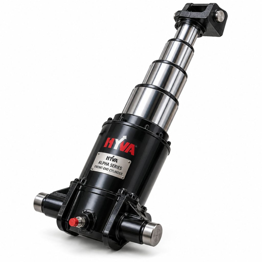
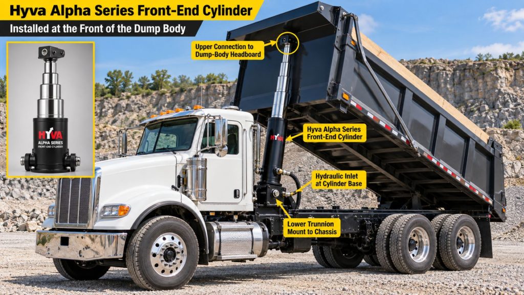
The Hyva Alpha Series Front-End Cylinder is a multistage telescopic hydraulic lifting cylinder designed for dump trucks, tipping bodies, and tipping semitrailers. It is installed near the front of the body and extends upward to rotate the body around its rear hinge.
The Alpha family includes multiple effective diameters, stroke lengths, stage counts, mounting arrangements, and heavy-duty configurations. This range allows the cylinder to be matched to different body lengths, rear overhangs, hinge locations, centers of gravity, payloads, and tipping angles.
Its telescopic design combines a long extended stroke with a comparatively short closed length. Hyva also designs these cylinders to limit unnecessary component and hydraulic-fluid weight, supporting faster tipping and lowering when correctly matched to the pump and valve.
The cylinder is one part of a complete tipping system. Safe operation also depends on the PTO, hydraulic pump, tipping valve, reservoir, hoses, brackets, body structure, rear hinges, controls, pressure settings, and vehicle stability.
Key Characteristics
- Multistage telescopic hydraulic-cylinder design
- Front-end mounting for rear-tipping bodies
- Multiple diameters, stages, strokes, and closed lengths
- Maximum working pressure commonly up to 250 bar
- Outer-cover and eye-mounted configurations
- Standard and heavy-duty models
- Hard-chromed stage options on applicable cylinders
- Compact closed length relative to extended stroke
- Designed to limit hydraulic-fluid requirements
- Application-specific body and chassis brackets
- Suitable for dump trucks and tipping semitrailers
- Model-specific tipping capacities approaching 100 tons
- Global Hyva component and service network
Major Components
- Outer cylinder tube
- Multiple telescopic extension stages
- Base or bottom mounting assembly
- Upper lifting bracket or piston eye
- Outer cover on applicable FC models
- Bottom eye on FEE and FSE configurations
- Stage bearings and guide rings
- Hydraulic seals
- Wear rings
- Dust seals and wipers
- Retaining rings
- Hydraulic inlet port
- Chassis mounting brackets
- Body lifting brackets
- Mounting pins and bushings
- Cylinder cradle where specified
- Hydraulic hose and fittings
- Identification label or model markings
Product Type and Construction
The Alpha Series is a single-acting telescopic lifting-cylinder family. Hydraulic pressure extends the cylinder, while the weight of the body normally retracts it as fluid returns to the reservoir.
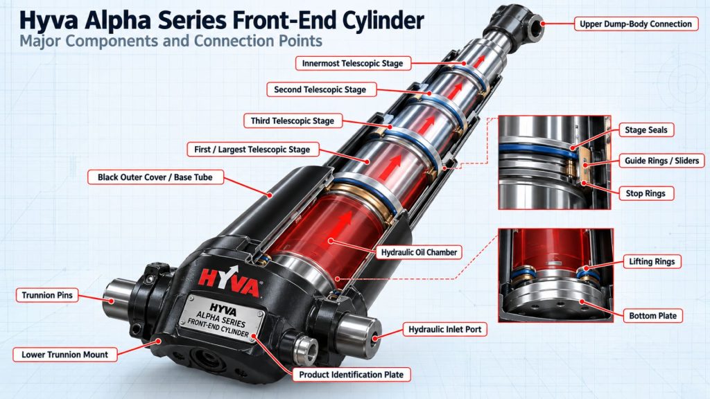
Nested steel tubes form the individual extension stages. The largest stage begins extending first, followed by progressively smaller stages as hydraulic fluid continues entering the cylinder.
Internal seals contain hydraulic pressure between the stages. Bearings, wear rings, and guide components help keep the extensions aligned and limit metal-to-metal contact during normal operation.
Standard cylinders are commonly finished in black, while applicable models may be ordered with hard-chromed stages for additional surface protection in demanding or corrosive environments.
How the Front-End Cylinder Works
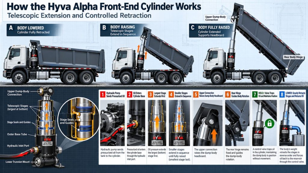
When the truck’s PTO drives the hydraulic pump, the pump sends pressurized oil through the tipping valve and into the cylinder. Pressure acts against the effective area of the largest available stage.
The cylinder begins extending and applies lifting force near the front of the dump body. Because the body is attached to rear hinges, this upward force rotates the body and increases the tipping angle.
As one telescopic stage reaches its designed extension, the next stage continues the lifting movement. The available lifting force changes as smaller-diameter stages extend.
When the operator selects lower, the tipping valve creates a controlled return path to the reservoir. Gravity lowers the body and pushes hydraulic fluid out of the cylinder. The valve must meter the return flow so the body does not descend too quickly.
Position and Function Within the Vehicle
The cylinder is installed near the front of the tipping body, usually immediately behind the cab or at the forward end of a semitrailer body. Its lower mount connects to the chassis or subframe, while its upper mount connects to the body structure.
This location allows a long cylinder stroke to produce the tipping angle needed for unloading. It also places substantial lifting forces into the forward body structure, cylinder brackets, subframe, chassis, and rear hinge assembly.
The Alpha cylinder is a lifting device only. It must not be used as a structural brace or be expected to resist side loads caused by uneven ground, off-center cargo, damaged hinges, or body misalignment.
Common Specifications
- Cylinder Type: Single-acting multistage telescopic front-end cylinder
- Primary Series: Hyva Alpha
- Common Type Codes: FC, FE, FEE, and FSE
- Common Effective First-Stage Diameters: Model-specific sizes such as approximately 110, 118, 129, 137, 149, 157, 169, 179, 191, and 214 millimeters
- Number of Extensions: Varies by cylinder model and required stroke
- Maximum Working Pressure: Commonly up to 250 bar on applicable models
- Oil-Inlet Connection: Model- and market-specific; one-inch BSP or NPT connections are used on many configurations
- Mounting Arrangement: Outer cover, piston eye, bottom eye, pin, or application-specific bracket system
- Available Stage Protection: Hard-chromed versions on applicable models
- Published Temperature Range: Commonly approximately -40°C to 80°C on applicable Alpha specifications
- Primary Applications: Rear-tipping dump bodies and tipping semitrailers
Stroke, closed length, working volume, total volume, weight, maximum pump flow, lowering time, cylinder load, and tipping capacity vary substantially by model. The exact Hyva specification sheet must be used for selection and installation.
Stroke, Lifting Capacity, and Operating Pressure
The required cylinder stroke is determined by the dump-body geometry and intended tipping angle. Longer bodies and different rear-hinge positions can require substantially different cylinder strokes.
Hyva Alpha models are available with multiple extension stages and total strokes measured in several meters. A representative FC A149 configuration uses three extensions and a total stroke of approximately 3,830 millimeters, while other Alpha models use different diameters, stages, and strokes.
Many Alpha specifications identify a maximum working pressure of 250 bar. The pressure-relief valve at the cylinder circuit must never be set above the maximum pressure approved for the exact cylinder and system.
The published tipping weight is based on defined body geometry, cylinder mounting, center of gravity, rear overhang, tipping angle, and maximum pressure. It is not a universal payload rating for every truck or trailer using that cylinder.
Cylinder Type and Mounting Design
The Alpha family includes several primary mounting arrangements:
- FC: Front-end cylinder with an outer cover
- FE: Front-end cylinder with a piston eye
- FEE: Front-end cylinder with a piston eye, bottom eye, and mounting pin
- FSE: Front-end cylinder with a piston eye and single bottom-eye configuration
The correct design depends on the body, chassis, subframe, available mounting space, required articulation, bracket dimensions, and regional body-building practices.
Standard and heavy-duty versions may use different brackets, bushings, pins, stage construction, and load limits. Components should not be interchanged solely because their outside dimensions appear similar.
Tipping Geometry and Load Distribution
Proper cylinder selection requires a tipping calculation. The calculation considers the body length, rear overhang, rear-hinge location, cylinder mounting position, bracket length, payload center of gravity, required tipping angle, and available hydraulic pressure.
The highest cylinder force is normally required at the beginning of the tipping cycle. At this point, the body is nearly horizontal and the cylinder has limited mechanical advantage over the load.
As the body rises, its center of gravity moves relative to the hinge and cylinder. The required lifting force changes throughout the cycle, as does the load carried by the extending cylinder stages.
Changing the body, rear overhang, hinge position, mounting brackets, or intended payload can invalidate the original cylinder selection. A new tipping calculation should be completed after significant equipment changes.
Pump Flow, Tipping Time, and Lowering Speed
The pump flow determines how quickly hydraulic fluid enters the cylinder. More flow generally produces a faster tipping cycle, but the flow must remain within the maximum approved for the exact cylinder and tipping system.
Published Alpha specifications can list maximum pump flows above 200 liters per minute on larger models. The permitted flow may differ depending on whether the system uses a Hyva pneumatic knock-off or other control arrangement.
Excessive flow can make the body rise too quickly, create severe pressure surges, shorten component life, and increase rollover risk. Insufficient flow may produce unnecessarily slow cycles and extended PTO operating time.
Lowering time must also remain within the cylinder and valve specifications. The tipping valve should meter returning oil so the body descends smoothly without creating excessive backpressure, heat, or impact when it reaches the chassis.
Hydraulic Circuit and Tipping-System Integration
The Alpha cylinder must be integrated with a correctly sized hydraulic system. A complete installation can include:
- Transmission power take-off
- Hydraulic pump
- Hydraulic-fluid reservoir
- Tipping valve
- Pressure-relief valve
- Raise, hold, and lower controls
- High-pressure hose and fittings
- Return hose
- Hydraulic filtration
- Pneumatic knock-off where equipped
- Body-position or tip-limit controls
- Cab warning indicators
- Chassis and body mounting brackets
The tipping valve must include pressure protection at the cylinder port, with its relief setting no higher than the maximum working pressure of the exact cylinder.
Controls and Electronic Integration
The cylinder itself is hydraulically operated and normally does not contain an electronic controller. System controls manage the PTO, pump, tipping valve, engine speed, and body movement.
Available control functions may include:
- PTO engagement and disengagement
- Body raise, hold, and lower
- Engine-speed control
- Pneumatic pump or valve knock-off
- Maximum tip-angle control
- Body-raised warning
- Tailgate interlock
- Parking-brake interlock
- Transmission interlock
- Low-fluid or high-temperature warning
- Hydraulic-pressure monitoring
- Remote operating controls
Automatic controls should supplement rather than replace operator observation. The driver remains responsible for monitoring the load, ground, body movement, overhead clearance, and vehicle stability.
Mounting and Installation
The lower cylinder bracket must be attached to a properly engineered chassis or subframe. The upper bracket must transfer lifting force into the body structure without distortion or localized cracking.
Mounting brackets must be positioned according to the approved tipping calculation and Hyva installation instructions. Incorrect spacing, bracket alignment, or pin clearance can introduce damaging side loads.
The cylinder must remain correctly aligned through its complete stroke. Hose routing must allow cylinder movement while preventing abrasion, stretching, kinking, heat exposure, and contact with the body or chassis.
The rear hinge assembly, body guides, subframe, and chassis must also be inspected and aligned before the tipping system enters service.
Vehicle, Body, and Frame Compatibility
Compatibility depends on the complete tipping vehicle rather than the cylinder diameter alone.
Selection factors include:
- Truck or trailer frame design
- Subframe dimensions and strength
- Body length and construction
- Body weight
- Intended payload and material density
- Payload center of gravity
- Rear overhang
- Rear-hinge position
- Required tipping angle
- Cylinder mounting position
- Closed cylinder length
- Required total stroke
- Maximum hydraulic pressure
- Available pump flow
- Cab and equipment clearance
A larger cylinder is not automatically safer. An incorrectly matched cylinder can overload the body, brackets, subframe, hinges, or chassis even when its hydraulic capacity appears adequate.
Common Applications
- Rear-tipping dump trucks
- End-dump semitrailers
- Construction dump bodies
- Aggregate-hauling vehicles
- Sand and gravel haulers
- Asphalt-hauling bodies
- Agricultural tipping trailers
- Mining and quarry vehicles
- Municipal dump trucks
- Heavy-duty tipper trucks
- Steel and aluminum tipping bodies
- Specialized material-hauling equipment
Advantages
- Long lifting stroke from a compact closed package
- Multiple diameters and stage configurations
- Broad selection of mounting arrangements
- Standard and heavy-duty models
- High lifting capacity for demanding tipping applications
- Relatively low hydraulic-fluid volume for the available stroke
- Can support fast tipping when matched to the correct pump
- Hard-chromed stage options for demanding environments
- Application-specific brackets and service components
- Established use in dump trucks and tipping semitrailers
- Global Hyva distribution and technical support
Limitations or Considerations
- Requires a complete application-specific tipping calculation
- Must not be subjected to side loads
- Does not provide structural support for a raised body
- Requires correctly engineered body and chassis brackets
- Maximum pressure and flow vary by model
- Incorrect pump flow can create unsafe body speed
- Body stability depends on level ground and balanced loading
- Long exposed stages require protection from physical damage
- Seal and guide wear can cause leakage or stage instability
- Contaminated hydraulic fluid can damage internal surfaces
- Body, frame, and hinge misalignment can damage the cylinder
- Replacement parts must match the complete cylinder code
Driver and Operator Experience
A correctly selected Alpha cylinder should raise the body smoothly at the designated engine speed. The extension stages should move without severe hesitation, binding, impact, or uncontrolled surging.
The operator should stop the tipping cycle if the truck leans, the body twists, a load hangs inside the body, a stage binds, hydraulic oil leaks, or the cylinder appears misaligned.
Material that freezes, sticks, bridges, or unloads from only one side can shift the vehicle’s center of gravity. The cylinder may have enough power to continue raising the body even when the truck or trailer is becoming unstable.
The body should lower smoothly and seat completely on the chassis before the PTO is disengaged and the vehicle is moved.
Tipping and Lowering Procedure
Operators must follow the truck, trailer, body, hydraulic-system, and Hyva instructions. A general operating sequence includes:
- Position the vehicle on firm, level ground.
- Check for overhead power lines, structures, and other obstructions.
- Confirm that the unloading area is clear.
- Apply the parking brakes and place the transmission in the required operating condition.
- Inspect the load for freezing, sticking, shifting, or uneven distribution.
- Open or release the tailgate using the approved procedure.
- Engage the PTO and establish the specified engine speed.
- Move the tipping control smoothly into raise.
- Monitor the cylinder, body, load, truck suspension, and ground continuously.
- Stop raising immediately if the vehicle leans or the body moves unevenly.
- Return the control to hold or neutral when the required angle is reached.
- Select lower and allow the body to descend at the approved speed.
- Confirm that the body is fully seated on the chassis.
- Disengage the PTO and verify that the tailgate is secured before travel.
This overview does not replace manufacturer instructions, operator training, fleet procedures, or jobsite safety requirements.
Inspection and Wear Points
- Outer cylinder tube
- Exposed telescopic stages
- Stage surfaces and hard-chrome finish
- Hydraulic seals and wipers
- Stage bearings and guide rings
- Upper lifting bracket or eye
- Lower chassis bracket or eye
- Mounting pins and retaining hardware
- Pin bushings
- Outer cover where equipped
- Hydraulic inlet and fittings
- Pressure hose
- Chassis and subframe
- Body lifting structure
- Rear hinges and hinge pins
- Body guides and stabilizing components
- Tipping valve and pressure-relief setting
- PTO, pump, reservoir, and controls
Lubrication and Hydraulic-Fluid Requirements
The hydraulic fluid lubricates the cylinder seals, bearings, guide surfaces, pump, and tipping valve. The selected fluid must meet Hyva requirements for viscosity, anti-wear protection, oxidation resistance, temperature range, and seal compatibility.
Mounting pins and bushings should be lubricated according to the cylinder, bracket, and body-builder instructions. Grease passages must remain clean and open.
Exposed cylinder stages should be kept clean and protected from weld spatter, concrete, asphalt, aggregate impact, corrosive chemicals, and improper cleaning tools.
Only clean hydraulic fluid should be added. Dirty containers, funnels, hoses, and service equipment can introduce damaging abrasive contamination.
Maintenance and Ownership Notes
Routine maintenance should include checking for oil leakage, cleaning exposed stages, inspecting stage surfaces, lubricating pins, examining brackets, testing controls, and monitoring tipping and lowering times.
Seal leakage should be corrected before contamination damages the cylinder stages or low fluid level causes pump problems. A wet stage should be cleaned and inspected to determine whether the leak comes from a damaged seal, scratched tube, worn bearing, or excessive side loading.
Loose pins, worn bushings, cracked brackets, distorted body structure, or damaged rear hinges can shift loads into the cylinder. These surrounding components should be inspected whenever abnormal cylinder wear is found.
Record the complete Hyva cylinder code before ordering seals, guides, pins, brackets, or a replacement cylinder. Similar Alpha cylinders can have different diameters, stages, strokes, mounts, and internal components.
Common Cylinder and Tipping-System Problems
- Cylinder will not extend: Low fluid level, an unengaged PTO, pump failure, incorrect valve position, blocked hose, open relief valve, excessive load, or internal cylinder damage may prevent lifting.
- Slow tipping: Low pump speed, worn pump, restricted hose, cold fluid, internal cylinder leakage, incorrect valve operation, or excessive load may reduce speed.
- Jerky stage movement: Air in the hydraulic system, contamination, damaged stage surfaces, worn guides, bent components, low fluid level, or excessive side loading may cause irregular extension.
- External hydraulic leakage: Worn seals, scratched stages, loose fittings, excessive pressure, contamination, or misalignment may allow fluid to escape.
- Cylinder binds or will not retract: Bent stages, damaged guides, side loading, body misalignment, contaminated surfaces, restricted return flow, or an obstructed hinge may prevent normal retraction.
- Body lowers too quickly: An incorrect valve setting, damaged tipping valve, oversized return path, control failure, or improper operating procedure may allow uncontrolled descent.
- Truck leans during tipping: Uneven ground, off-center loading, material sticking on one side, tire or suspension problems, body distortion, or cylinder misalignment may be responsible.
- Bracket or pin wear: Inadequate lubrication, loose fasteners, incorrect alignment, excessive clearance, overloading, or repeated side loading can accelerate wear.
- Stage corrosion or scoring: Moisture, road chemicals, abrasive contamination, physical impacts, damaged chrome, or improper cleaning can damage the working surfaces.
Safety and Service Precautions
Never work beneath a raised dump body unless it is secured by an approved mechanical body prop or support. The hydraulic cylinder must never be used as the only support during inspection or repair.
Lower the body, disengage the PTO, shut down the engine, secure the vehicle, and relieve hydraulic pressure before opening the system or removing components.
Never search for a hydraulic leak with a hand. Escaping high-pressure fluid can penetrate skin and requires immediate emergency medical treatment.
The cylinder should not be exposed to side loading. Tipping should stop immediately if the body twists, the vehicle leans, the cylinder bends away from its normal alignment, or the load hangs inside the body.
Keep the raised body and cylinder away from overhead power lines. Contact or close approach can cause electrocution even when the cylinder does not physically touch the conductor.
Identification Information
The cylinder model code contains important information about its type, effective diameter, stage count, stroke, mount, hydraulic connection, closed length, and available options.
- Hyva manufacturer name
- Alpha Series designation
- Complete cylinder model code
- Hyva item or part number
- FC, FE, FEE, or FSE cylinder type
- Effective first-stage diameter
- Number of extensions
- Total stroke
- Closed length
- Maximum working pressure
- Maximum approved pump flow
- Working and total oil volume
- Maximum cylinder load
- Standard or heavy-duty configuration
- Hard-chromed option where equipped
- Bracket, pin, and bushing information
- Truck, trailer, and body identification
Do not identify a replacement cylinder solely by outside diameter or total length. The complete Hyva code and application geometry must be verified.
Buying Considerations
- Identify the body length and construction
- Record the body’s empty weight
- Determine the intended payload and material density
- Calculate the loaded center of gravity
- Measure the rear overhang and hinge position
- Determine the required tipping angle
- Calculate the required cylinder stroke
- Confirm the available closed-length space
- Select the correct FC, FE, FEE, or FSE mounting type
- Verify maximum working pressure
- Determine the required pump flow and tipping time
- Confirm working and total oil volume
- Match the chassis and body brackets
- Select standard or heavy-duty construction
- Consider hard-chromed stages for corrosive service
- Verify cab, frame, and equipment clearance
- Confirm replacement-parts availability
- Use a qualified tipping-system engineer or body builder
Variants and Configurations
- FC front-end cylinder with outer cover
- FE front-end cylinder with piston eye
- FEE cylinder with piston eye, bottom eye, and pin
- FSE cylinder with piston eye and single bottom eye
- Different effective first-stage diameters
- Different numbers of telescopic extensions
- Different total strokes and closed lengths
- Standard-duty configurations
- Heavy-duty configurations
- Hard-chromed stage options
- Different upper and lower bracket designs
- Different hydraulic-port configurations
- Application-specific K and L dimensions
- Different working volumes and flow limits
Comparison to Similar Equipment
Compared with the Mailhot G3 Telescopic Hydraulic Cylinder, the Hyva Alpha provides an alternative front-end telescopic lifting system with different stage designs, brackets, model coding, and application calculations.
Compared with the Custom Hoists 500 Series Underbody Hoist, the Alpha cylinder mounts at the front of the dump body. An underbody hoist applies lifting force from beneath the body through a different mechanical arrangement.
Compared with a conventional straight hydraulic cylinder, the telescopic Alpha design produces a much longer extended stroke relative to its closed length.
Compared with a scissor hoist, a front-end cylinder uses fewer mechanical linkage components but places major lifting forces into the front body structure and rear hinges.
Best Fit For
- Rear-tipping dump trucks
- End-dump semitrailers
- Long-stroke tipping applications
- Construction and aggregate vehicles
- Heavy-duty tipper trucks
- Mining and quarry operations
- Applications requiring a compact closed cylinder length
- Vehicles needing model-specific standard or heavy-duty cylinders
- Fleets with access to Hyva parts and service support
- New body installations engineered around an Alpha cylinder
- Vehicles replacing an identified Hyva Alpha cylinder
Related Vehicle and Trailer Types
- Complete Guide to Semi Truck Types
- Class 6 vs Class 7 vs Class 8 Trucks
- Dump Trucks
- Dump Trailers
- End-Dump Trailers
- Vocational Trucks
- Construction Trucks
- Municipal Trucks
- Heavy Haul Freight Guide
Related Truck and Trailer Models
- Mack Granite
- Kenworth T880
- Peterbilt 567
- International HX Series
- Western Star 47X
- Western Star 49X
- Volvo VHD
- Freightliner 114SD
- Travis Dump Trailer
- MAC Dump Trailer
Related PTO and Hydraulic System Types
- Power Take-Off Systems
- Hydraulic Pumps & Motors
- Wet Kits & Complete Hydraulic Systems
- Hydraulic Cylinders & Dump Hoists
- Hydraulic Valves, Controls & Reservoirs
- Hydraulic Hoses, Fittings & Filtration
- Front-End Telescopic Cylinders
- Underbody Dump Hoists
Related PTO and Hydraulic Products
- Mailhot G3 Telescopic Hydraulic Cylinder
- Custom Hoists 500 Series Underbody Hoist
- Muncie WETLINE Hydraulic System
- Parker Chelsea Wetline Hydraulic System
- Permco DM-640 Dump Pump
- Permco P5151 Hydraulic Pump
- Parker F1 Hydraulic Pump
- Muncie E Series Hydraulic Pump
- Muncie V Series Hydraulic Directional Control Valve
Related Equipment Systems
- PTO & Hydraulic Systems
- Transmissions
- Suspension Systems
- Axles & Differentials
- Brake Systems
- Electrical Systems
- Tires & Wheels
Related Guides
- PTO & Hydraulic System Guides
- How Commercial Truck PTO and Hydraulic Systems Work
- Commercial Truck Power Take-Off Types Explained
- How to Choose a PTO and Hydraulic Pump
- Commercial Truck Wet Kits Explained
- How to Inspect and Maintain Truck Hydraulic Systems
- How Dump Truck Hydraulic Systems Work
- Front-End Cylinder vs Underbody Hoist
- How to Select a Dump Truck Hydraulic Cylinder
Regulatory and Compliance Notes
The cylinder’s lifting capacity does not increase the truck or trailer’s certified gross vehicle weight rating, gross axle weight ratings, payload capacity, or legal road-weight limits.
The completed tipping system must comply with applicable vehicle, body-builder, workplace, hydraulic-equipment, and highway-safety requirements. The installation must preserve safe operation of the frame, suspension, brakes, steering, fuel system, electrical equipment, and rear hinges.
Mechanical body props, warning labels, controls, emergency procedures, and operator training must meet applicable regulations and industry standards.
Hydraulic-fluid leaks and spills may be subject to environmental and workplace reporting requirements. Fleets should maintain appropriate spill-control equipment and procedures.
Real World Operating Notes
Most rollover risk develops from vehicle position, cargo behavior, and body movement rather than from a lack of cylinder lifting power. A powerful cylinder can continue raising an unstable body unless the operator stops the cycle.
A dump body should be lowered immediately if one side rises faster than the other, material sticks inside the body, the rear wheels begin unloading unevenly, or the ground begins settling.
Cylinder leakage is not always caused by worn seals. Scratched stages, bent tubes, worn guides, contaminated fluid, excessive pressure, damaged hinges, and bracket misalignment should also be investigated.
The correct replacement cylinder must reproduce the original mounting geometry and stroke. Installing a cylinder that is merely similar in length can alter the tipping angle, body clearance, load path, and maximum component forces.
Frequently Asked Questions
What is the Hyva Alpha Series Front-End Cylinder?
It is a multistage telescopic hydraulic cylinder designed to raise rear-tipping dump bodies and tipping semitrailers.
Where is the Alpha cylinder installed?
It is installed near the front of the tipping body, with one end connected to the chassis or subframe and the other connected to the body structure.
What do FC, FE, FEE, and FSE mean?
They identify different cylinder and mounting designs, including outer-cover, piston-eye, and bottom-eye configurations.
What is the maximum working pressure?
Many Alpha models are rated for a maximum working pressure of 250 bar, but the specification for the exact cylinder must be confirmed.
How much weight can an Alpha cylinder tip?
Tipping capacity is model- and installation-specific. Hyva offers configurations covering a broad range of calculated tipping weights, with some applications approaching 100 tons.
Can the cylinder support a raised body during service?
No. A raised body must be secured with an approved mechanical body prop or support before anyone works beneath it.
Can the cylinder handle side loading?
No. The Alpha cylinder is a lifting device and should not be used as a structural member or exposed to side loads.
What causes jerky cylinder extension?
Possible causes include air in the system, contamination, low fluid level, damaged stages, worn guides, bent components, misalignment, or unstable pump flow.
Are hard-chromed stages available?
Hyva identifies hard-chromed versions for applicable Alpha cylinder models.
How can the correct replacement cylinder be identified?
Use the complete Hyva cylinder code, item number, type, diameter, number of extensions, stroke, closed length, mount, pressure, and original vehicle geometry.
Availability and Where to Find
Hyva Alpha Series cylinders, brackets, pins, bushings, seal kits, stage components, controls, valves, and related hydraulic-system parts may be available through Hyva distributors, dump-body builders, trailer manufacturers, commercial-truck equipment dealers, hydraulic repair facilities, and heavy-duty parts suppliers.
Availability depends on the complete cylinder code, market, mounting arrangement, stage count, stroke, pressure rating, heavy-duty designation, and surface-protection options.
Current product information, technical support, cylinder-selection assistance, and distributor resources are available through the Hyva website.
Support Trucking Families
Truck Equipment Atlas supports the mission of Grey Cross, a nonprofit dedicated to helping families of truck drivers who lose their lives while on the road. As the site grows, part of its mission is to bring awareness and support to these families.
Podcast or Video Section
Learn More Through Audio and Video
Truck Equipment Atlas will continue expanding with podcast episodes, interviews, and equipment breakdowns to help drivers and fleets better understand trucks and equipment.
Follow the Growth of Truck Equipment Atlas
Truck Equipment Atlas continues to expand with new truck profiles, trailer coverage, diesel engine pages, equipment system resources, manufacturer information, and educational guides.
Visit our Site Updates page to explore recent additions, project milestones, and upcoming resources as we continue building one of the industry’s growing commercial trucking equipment reference libraries.
View the Latest Site Updates: Truck Equipment Atlas Site Updates