
Quick Facts
- Manufacturer: Muncie Power Products
- Product Family: V Series
- Product Type: Sectional hydraulic directional control valve
- Major Current Models: V050, V080, V130, and V250
- Maximum Published Flow: Model-specific, from 16 to 75 GPM
- Maximum Published Pressure: Model- and configuration-specific, reaching approximately 5,440 psi on selected models
- Circuit Options: Open-center and application-specific closed-center arrangements
- Control Options: Manual, cable, pneumatic, hydraulic-pilot, electric, and electrohydraulic options, depending on model
- Primary Applications: Dump bodies, refuse equipment, snow and ice equipment, utility vehicles, recovery equipment, and specialized vocational machinery
- Primary Function: Directs pressurized hydraulic oil between the pump, actuator, and reservoir
- Production Status: Current family with model-specific availability
Overview
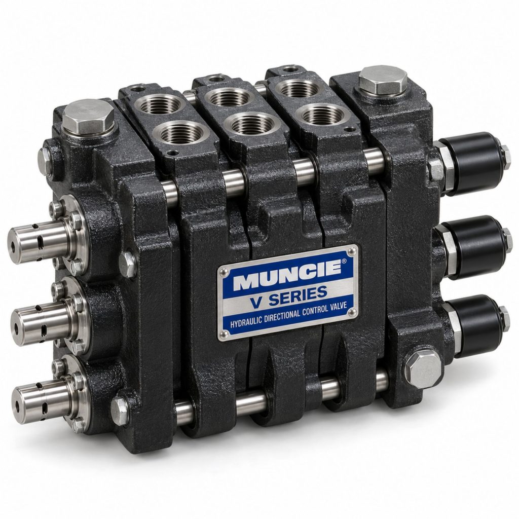
The Muncie V Series is a family of configurable sectional directional control valves used to manage hydraulic oil flow in commercial trucks, trailers, and vocational equipment. Each valve assembly can contain an inlet section, one or more work sections, and an outlet section selected for the required hydraulic circuit.
Moving a valve spool connects the pump supply to the selected actuator port while providing a return path from the opposite side of the actuator to the reservoir. Returning the spool to neutral changes or interrupts the oil paths according to the selected spool and circuit configuration.
The V Series includes multiple valve sizes rather than one universal valve. The smaller V050 serves lower-flow applications, while the V080, V130, and V250 accommodate progressively greater hydraulic-flow requirements. Spool functions, controls, positioners, relief valves, port sizes, and outlet arrangements must be selected for the individual machine.
Key Characteristics
- Modular sectional directional-control design
- Multiple valve sizes for different flow requirements
- High-grade iron castings on applicable models
- Nickel-plated or hard-chrome spool options, depending on model
- Precision machining intended to limit internal spool leakage
- Multiple spool functions and neutral arrangements
- Manual and remotely operated control options
- Different spool positioners and detent configurations
- Open-center circuit configurations
- Closed-center options on applicable models
- Power-beyond or high-pressure carryover options
- Work-port relief and anti-cavitation options
- Expandable work sections for multifunction equipment
- Application-specific inlet, outlet, and port arrangements
Major Components
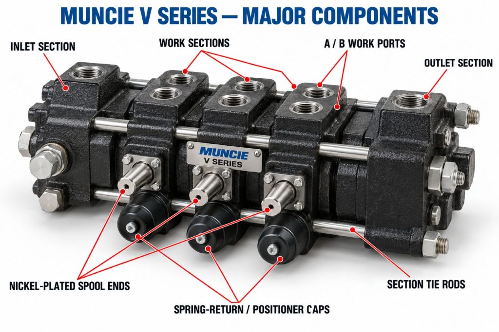
- Inlet section
- Main pressure-relief valve
- Individual work sections
- Directional-control spools
- Spool seals
- Load-check valves
- Work-port relief valves where specified
- Anti-cavitation valves where specified
- Combination relief and anti-cavitation valves
- Manual lever or remote-control mechanism
- Spring-return or detent positioner
- Pilot-operated check valve where equipped
- Mid-inlet or mid-outlet section where required
- Outlet section
- Power-beyond or closed-center sleeve
- Section tie rods and fasteners
- Hydraulic ports and fittings
Product Type and Construction
The V Series uses sectional construction. Separate inlet, work, and outlet sections are assembled into a complete valve bank. This design allows the valve to be configured around the number and type of hydraulic functions required by the vehicle or machine.
Each work section contains a precision-fitted spool that moves within machined hydraulic passages. Muncie uses high-grade iron castings and wear-resistant spool finishes on applicable models to support high-pressure mobile applications.
Sectional construction also permits different spool functions, controls, detents, port accessories, and relief settings within the same valve bank. The assembled valve must still remain within the flow, pressure, back-pressure, and section-count limits established for the selected model.
How the Hydraulic Directional Control Valve Works
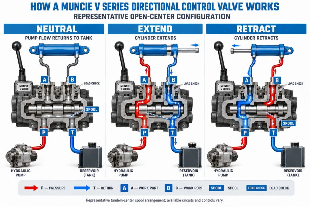
Hydraulic oil enters the valve through the inlet section. In an open-center circuit, oil normally passes through the valve’s open center passage and returns to the reservoir when all spools are in neutral.
When the operator shifts a spool, the valve redirects pump flow to one actuator port. Oil returning from the opposite side of a double-acting cylinder or motor flows through the other work port and back toward the reservoir.
Moving the spool in the opposite direction reverses the pressure and return paths. A single-acting spool supplies oil to raise or extend an actuator and opens the return path when the actuator is lowered by gravity or an external load.
The exact neutral, raise, lower, motor, float, and regenerative functions depend on the spool selected for each work section.
Position and Function Within the Vehicle
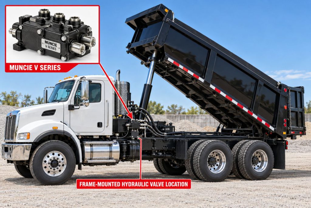
The valve bank is installed between the hydraulic pump and the equipment’s cylinders or motors. Its location may be on the chassis, behind the cab, inside a protected equipment compartment, beneath a body, or directly on the vocational body.
The valve controls which hydraulic function receives pump flow, the direction in which the actuator moves, and whether the actuator is held, allowed to float, or returned to neutral. Relief and accessory valves can also protect individual circuits and control actuator behavior.
Common Specifications
- Valve Type: Sectional hydraulic directional control valve
- Current Family Sizes: V050, V080, V130, and V250
- V050 Maximum Flow: 16 GPM
- V080 Maximum Flow: Approximately 30 GPM
- V130 Maximum Flow: 55 GPM
- V250 Maximum Flow: 75 GPM
- Maximum Pressure: Model- and configuration-specific, reaching approximately 5,440 psi on selected models
- Construction: High-grade iron sections on applicable models
- Spool Finish: Nickel plated or hard chrome, depending on model and configuration
- Circuit Options: Open center with closed-center and power-beyond options on applicable models
- Controls: Manual and remote-control arrangements
- Configuration: Application-specific inlet, work, mid, and outlet sections
Flow, Pressure, and Operating Capacity
The V Series covers different hydraulic-flow ranges:
- V050: Compact valve with a nominal flow near 13 GPM and maximum published flow of 16 GPM.
- V080: Intermediate valve intended for flow capacities up to approximately 30 GPM.
- V130: Mid-range valve with maximum published flow of 55 GPM.
- V250: Higher-flow valve with maximum published flow of 75 GPM.
Maximum allowable pressure can change with the valve model, number of work sections, circuit design, control arrangement, and port option. Every section and accessory must be rated for the system’s maximum pressure and expected pressure spikes.
Selecting a valve that is too small can create excessive pressure loss, heat, slow actuator performance, and reduced system efficiency. An unnecessarily large valve can add weight, cost, and installation space without improving performance.
Spool Functions and Circuit Design
Available spool functions depend on the valve model and application. Common configurations include:
- Single-acting cylinder spool
- Double-acting cylinder spool
- Hydraulic-motor spool
- Float spool
- Raise, hold, and lower dump-body function
- Spring-centered spool
- Three-position detent spool
- Four-position spool with float
- Regenerative function where specified
- Application-specific special spools
The spool’s internal lands and grooves determine the oil paths in neutral and each operating position. A spool intended for a hydraulic motor may not safely provide the same neutral behavior as one designed for a cylinder.
Air, Hydraulic, and Electronic Controls
V Series valve sections may use different control mechanisms depending on the model and vehicle. Available arrangements can include:
- Direct manual lever
- Mechanical cable control
- Pneumatic spool control
- Hydraulic-pilot control
- Electric-solenoid control
- Electrohydraulic proportional control
- Remote body-control interface
- Spring-return positioner
- Mechanical or hydraulic detent
Remote controls must move the correct spool through its complete intended travel without causing partial engagement. Electrical and pneumatic controls require properly routed wiring or air lines, suitable interlocks, and protection from heat, water, impact, and abrasion.
Relief Valves, Power Beyond, and Load Control
The inlet section may include a main pressure-relief valve that limits maximum circuit pressure by diverting oil when the preset pressure is reached. Work-port relief valves can provide separate protection for individual actuator circuits.
Anti-cavitation valves can admit replacement oil when an actuator moves faster than the pump can supply its inlet side. Pilot-operated check valves may be used where the application requires additional load holding.
Power-beyond or high-pressure carryover allows pressurized oil to supply another downstream valve while providing a separate return path to the reservoir. The correct outlet sleeve and plumbing arrangement are critical because an incorrectly installed power-beyond circuit can damage the valve or create uncontrolled equipment movement.
Mounting and Installation
The valve should be mounted to a rigid structure that supports its weight without twisting the sectional assembly. The location should protect the valve from road debris, exhaust heat, direct impacts, excessive vibration, and contamination while still allowing inspection and service.
Hydraulic ports must be connected according to the approved circuit diagram. Pump, tank, work-port, power-beyond, and load-sense connections must never be identified by physical appearance alone.
Hoses should be sized for expected flow and routed to prevent sharp bends, kinking, abrasion, heat exposure, and mechanical strain. The valve-bank tie rods and mounting fasteners must be tightened according to Muncie’s specifications.
Vehicle and Hydraulic-System Compatibility
Compatibility depends on:
- Required hydraulic-flow rate
- Maximum system pressure
- Allowable return-line back pressure
- Open- or closed-center pump system
- Number of hydraulic functions
- Single- or double-acting actuators
- Cylinder and hydraulic-motor requirements
- Spool neutral configuration
- Required manual or remote controls
- Port size and thread type
- Relief-valve requirements
- Power-beyond requirements
- Available mounting space
- Hydraulic-fluid type and temperature
- Filtration and cleanliness requirements
The correct valve cannot be selected from maximum flow alone. Spool function, circuit type, control method, outlet configuration, accessories, and actuator behavior must also match the equipment.
Common Applications
- Dump trucks
- Dump trailers
- Refuse trucks
- Snowplows and salt spreaders
- Utility and service trucks
- Recovery and towing equipment
- Roll-off trucks
- Vacuum trucks
- Truck-mounted cranes
- Material-handling equipment
- Municipal vehicles
- Construction equipment
- Specialized vocational machinery
Advantages
- Multiple valve sizes cover different hydraulic-flow ranges
- Sectional construction supports application-specific configurations
- Multiple spool functions are available
- Manual and remote-control options
- High-pressure construction on applicable models
- Wear-resistant spool finishes
- Power-beyond and closed-center options on applicable models
- Work-port relief and anti-cavitation options
- Compact packaging relative to available flow
- Individual sections can be identified and serviced
- Suitable for multifunction vocational equipment
- Supported by Muncie technical literature and distribution
Limitations or Considerations
- Requires correct sizing for flow, pressure, and back pressure
- Spool functions are not universally interchangeable
- Incorrect power-beyond installation can cause serious damage
- Contaminated oil can damage spools and precision-machined passages
- Improper tie-rod torque can cause leakage or spool binding
- Valve configuration can become complex on multifunction equipment
- Remote controls require additional air, electrical, cable, or pilot components
- Internal leakage can increase as spools and bores wear
- Incorrect relief settings can damage actuators or prevent normal operation
- Replacement sections must match the complete valve assembly
Driver and Operator Experience
A properly configured V Series valve should provide predictable equipment movement with clear control response. Lever effort, spool travel, detent feel, and actuator speed depend on the control and hydraulic configuration.
Slow, jerky, drifting, or unexpectedly fast movement can indicate incorrect pump speed, restricted plumbing, aerated oil, contamination, valve wear, improper relief adjustment, or an actuator problem.
Operators should understand the function of every control before engaging the PTO. Controls should be clearly identified so that one hydraulic function cannot be mistaken for another.
Operating Procedure
A general operating sequence includes the following steps. The vehicle, PTO, pump, valve, and equipment manufacturers’ instructions take priority.
- Park or position the vehicle according to the equipment procedure.
- Apply the parking brake and establish the required safety zone.
- Verify that all hydraulic controls are in neutral.
- Engage the PTO at the approved transmission and engine conditions.
- Operate the required valve control smoothly.
- Monitor actuator movement, system pressure, and equipment stability.
- Return the control to neutral if movement becomes abnormal.
- Complete the operating cycle without exceeding actuator travel.
- Return all valve sections to their required neutral positions.
- Disengage the PTO before driving unless the system is approved for mobile operation.
Inspection and Wear Points
- Valve sections for cracks or external leakage
- Section joints and seals
- Spools for sticking, scoring, or contamination
- Manual levers and pivot points
- Control cables and linkages
- Pneumatic or hydraulic pilot lines
- Electrical connectors and solenoids
- Spring-return and detent mechanisms
- Relief-valve adjustments and protective caps
- Work-port accessory valves
- Power-beyond and outlet components
- Hydraulic hoses and fittings
- Valve-bank tie rods and mounting fasteners
- Reservoir oil level and condition
Lubrication Requirements
The valve’s internal moving parts are lubricated by the hydraulic oil. Use fluid meeting the viscosity, temperature, additive, and seal-compatibility requirements established for the complete hydraulic system.
External lever pivots, cables, and linkages should be serviced according to their manufacturers’ instructions. Do not apply lubricants that attract contamination to exposed spool or seal areas.
Maintenance and Ownership Notes
Maintain the specified hydraulic-fluid cleanliness level and replace filters according to the equipment schedule. Dirt, metal particles, water, and degraded oil can damage the close-fitting spools and valve bores.
Inspect valve-bank joints, ports, controls, hoses, and mounting hardware regularly. Relief pressure should be tested with calibrated equipment rather than adjusted in response to slow or weak equipment operation without first diagnosing the cause.
Replacement sections and parts must match the valve model, assembly code, spool function, port arrangement, control, and positioner. Changing one section can affect the operation and pressure capability of the entire valve bank.
Common Hydraulic Valve Problems
- Spool will not move: Contamination, corrosion, mechanical damage, excessive section torque, a failed control, or actuator pressure may cause binding.
- Actuator moves slowly: Low pump flow, restricted plumbing, an undersized valve, partial spool travel, internal leakage, or excessive load may reduce speed.
- Actuator drifts in neutral: Worn spool clearances, damaged seals, leaking load checks, cylinder bypass, or an incorrect spool configuration may cause movement.
- Valve overheats: Excessive pressure drop, prolonged relief operation, an incorrect center configuration, restricted return flow, or an undersized valve may generate heat.
- External leakage: Loose fittings, damaged port threads, failed section seals, spool-seal wear, cracked castings, or incorrect tie-rod torque may allow oil to escape.
- Control will not return to neutral: A damaged spring, contaminated positioner, bent linkage, frozen cable, air-control problem, or solenoid failure may be responsible.
- Relief valve operates continuously: Overloading, a blocked actuator, incorrect relief adjustment, improper plumbing, or a valve too small for system flow may keep the circuit on relief.
- Downstream valve does not operate: An incorrect power-beyond sleeve, blocked carryover passage, improper outlet plumbing, or incompatible center configuration may interrupt downstream flow.
Safety and Service Precautions
- Lower or mechanically secure all raised equipment before service.
- Shut down the power source and relieve stored hydraulic pressure.
- Follow lockout and tagout procedures.
- Do not search for hydraulic leaks with bare hands.
- Treat hydraulic fluid-injection injuries as medical emergencies.
- Keep personnel away from cylinders, motors, linkages, and pinch points.
- Do not change relief pressure without calibrated test equipment.
- Verify port identity before connecting hydraulic lines.
- Cap open hoses and ports immediately to prevent contamination.
- Use replacement parts approved for the exact valve model.
- Do not loosen valve sections while the system is pressurized.
- Test repaired equipment in a controlled area before returning it to service.
Identification Information
Record the following information before ordering a valve, section, seal kit, spool, control, or accessory:
- V Series model family
- Complete valve assembly number
- Valve-bank configuration code
- Serial or production information
- Number of work sections
- Spool function for each section
- Control type for each section
- Positioner or detent arrangement
- Inlet and outlet configuration
- Port sizes and thread types
- Relief-valve type and setting
- Power-beyond or closed-center components
- Work-port accessories
- Vehicle and equipment application
Do not identify a replacement valve from physical appearance alone. Similar-looking sections may have different spool functions, pressure ratings, port arrangements, or neutral circuits.
Buying Considerations
- Calculate the required pump-flow range.
- Confirm maximum system pressure and back pressure.
- Select the correct V Series valve size.
- Determine whether the circuit is open or closed center.
- Identify every required hydraulic function.
- Select the correct spool for each actuator.
- Choose manual, cable, pneumatic, hydraulic, or electric controls.
- Specify spring-return, detent, or float positioners.
- Confirm inlet, outlet, work-port, and thread sizes.
- Determine relief and anti-cavitation requirements.
- Confirm whether power beyond is needed.
- Review filtration and hydraulic-fluid requirements.
- Verify available mounting and service space.
- Use Muncie’s configuration tools or an authorized distributor.
Variants and Configurations
- V050 compact directional control valve
- V080 intermediate-flow directional control valve
- V130 mid-range directional control valve
- V250 high-flow directional control valve
- Single- and double-acting cylinder spools
- Hydraulic-motor spools
- Float spools
- Manual lever controls
- Cable and pneumatic controls
- Hydraulic-pilot and electric controls
- Spring-return and detent positioners
- Open-center configurations
- Closed-center options
- Power-beyond configurations
- Work-port relief and anti-cavitation options
- Different port and thread arrangements
Comparison to Similar Equipment
Compared with a monoblock directional valve, the Muncie V Series uses sectional construction that can be configured with different work sections and control functions. A monoblock valve may be smaller and simpler but provides less configuration flexibility.
Compared with a basic dump-body tipping valve, the V Series can control multiple cylinders, motors, and equipment functions within one valve bank. A dedicated tipping valve may be better suited to a simple single-function dump system.
Compared with a load-sensing valve system, many V Series applications use open-center hydraulic architecture. The correct design depends on the pump, duty cycle, energy-efficiency requirements, and number of simultaneous functions.
Best Fit For
- Vocational vehicles requiring multiple hydraulic functions
- Dump, refuse, snow, utility, and recovery equipment
- Applications requiring configurable sectional valves
- Systems requiring manual or remote controls
- Equipment needing power-beyond capability
- High-pressure mobile hydraulic systems
- Fleets requiring manufacturer-supported valve configurations
- Installations with properly matched pumps, actuators, and filtration
Related Vehicle and Trailer Types
- Commercial Trucks
- Vocational Trucks
- Dump Trailers
- Refuse Trucks
- Utility Trucks
- Recovery Vehicles
- Municipal Trucks
- Vacuum Trucks
Related Truck and Trailer Models
- Mack Granite
- Kenworth T880
- Peterbilt 567
- Freightliner 114SD
- International HX Series
- Western Star 47X
- Western Star 49X
- Volvo VHD
Related PTO and Hydraulic System Types
- Power Take-Off Systems
- Hydraulic Pumps & Motors
- Wet Kits & Complete Hydraulic Systems
- Hydraulic Cylinders & Dump Hoists
- Hydraulic Valves, Controls & Reservoirs
- Hydraulic Hoses, Fittings & Filtration
Related PTO and Hydraulic Products
- Muncie WETLINE Hydraulic System
- Muncie E Series Hydraulic Pump
- Muncie TG Series Power Take-Off
- Muncie CS6 Series Power Take-Off
- Muncie FR6Q Power Take-Off
- Permco DM-640 Dump Pump
- Parker F1 Hydraulic Pump
- Parker F2 Twin-Flow Hydraulic Pump
- Mailhot G3 Telescopic Hydraulic Cylinder
- Custom Hoists 5000 Series Telescopic Hydraulic Cylinder
Related Equipment Systems
- PTO & Hydraulic Systems
- Transmissions
- Electrical Systems
- Brake Systems
- Suspension Systems
- Axles & Differentials
- Telematics & ELD Systems
Related Guides
- PTO & Hydraulic System Guides
- How Commercial Truck PTO and Hydraulic Systems Work
- Commercial Truck Power Take-Off Types Explained
- How to Choose a PTO and Hydraulic Pump
- Commercial Truck Wet Kits Explained
- How to Inspect and Maintain Truck Hydraulic Systems
- Hydraulic Directional Control Valves Explained
- Open-Center vs Closed-Center Hydraulic Systems
- How to Select a Mobile Hydraulic Control Valve
Regulatory and Compliance Notes
The valve and completed hydraulic system must be installed so that equipment cannot move unexpectedly or interfere with safe vehicle operation. Controls should be clearly identified and protected against unintended activation.
Hydraulic-system modifications must preserve the vehicle’s braking, steering, lighting, stability, electrical, exhaust, and fuel-system performance. Final-stage manufacturers and equipment installers are responsible for applicable certification and compliance requirements.
Employers and technicians must follow applicable stored-energy, lockout, machine-guarding, raised-equipment, and hydraulic fluid-injection safety requirements.
Real World Operating Notes
A valve can be large enough for the pump’s rated flow but still be incorrect if its spool or neutral circuit does not match the actuator. Valve selection should begin with the complete hydraulic schematic rather than only the desired GPM rating.
Continuous operation against the relief valve wastes power and creates heat. If an actuator repeatedly stalls or reaches the end of its travel while the pump continues supplying oil, the operating procedure or control system should be corrected.
Jerky movement is not always caused by the valve. Air entering the pump inlet, low reservoir level, contaminated oil, damaged cylinders, restricted hoses, and unstable pump speed can create similar symptoms.
Frequently Asked Questions
What is the Muncie V Series?
It is a family of sectional hydraulic directional control valves used to direct pump flow to cylinders, hydraulic motors, and other equipment functions.
Is the V Series one valve model?
No. The family includes different valve sizes, including the V050, V080, V130, and V250.
What is the maximum V Series flow rate?
It depends on the model. Published maximum flow ranges from 16 GPM for the V050 to 75 GPM for the V250.
What does a directional control valve do?
It changes the paths followed by hydraulic oil so the selected cylinder or motor can move, stop, reverse, hold, or float.
Can the valve control more than one function?
Yes. Sectional construction allows multiple work sections to be assembled into one valve bank.
Does the V Series support power beyond?
Power-beyond or high-pressure carryover options are available on applicable models and configurations.
Can a V Series section be replaced independently?
Sectional construction permits individual component service, but the replacement must match the valve model, spool function, controls, porting, accessories, and complete assembly requirements.
Why does a hydraulic function drift in neutral?
Possible causes include internal valve leakage, actuator bypass, a damaged load-holding valve, contamination, worn spool clearances, or an incorrect spool configuration.
How is the correct valve identified?
Use the complete Muncie valve model and assembly code, along with the number of sections, spool functions, controls, port sizes, circuit type, and relief requirements.
Can the relief valve be adjusted to make the equipment lift more?
Relief pressure should only be tested and adjusted according to approved specifications using calibrated equipment. Increasing pressure can overload the pump, valve, actuator, hoses, structure, and vehicle.
Availability and Where to Find
Muncie V Series valve assemblies, work sections, controls, positioners, relief components, seal kits, and service parts may be available through Muncie Power Products distributors, truck-equipment dealers, hydraulic specialists, body builders, and vocational-equipment installers.
Availability depends on the valve model, section count, spool functions, control types, porting, and accessory configuration. Provide the complete assembly code and equipment information before ordering.
Current product information, valve-configuration resources, technical literature, parts support, and distributor information are available through the Muncie Power Products control-valve website.
Support Trucking Families
Truck Equipment Atlas supports the mission of Grey Cross, a nonprofit dedicated to helping families of truck drivers who lose their lives while on the road. As the site grows, part of its mission is to bring awareness and support to these families.
Podcast or Video Section
Learn More Through Audio and Video
Truck Equipment Atlas will continue expanding with podcast episodes, interviews, and equipment breakdowns to help drivers and fleets better understand trucks and equipment.
Follow the Growth of Truck Equipment Atlas
Truck Equipment Atlas continues to expand with new truck profiles, trailer coverage, diesel engine pages, equipment system resources, manufacturer information, and educational guides.
Visit our Site Updates page to explore recent additions, project milestones, and upcoming resources as we continue building one of the industry’s growing commercial trucking equipment reference libraries.
View the Latest Site Updates: Truck Equipment Atlas Site Updates