
Quick Facts
- Manufacturer: Mailhot Industries
- Product Series: G3 Series
- Product Type: Telescopic hydraulic cylinder
- Operating Principle: Single-acting hydraulic extension with gravity-powered retraction
- Mounting Design: Trunnion-mounted with protective cover
- Number of Stages: Model-specific, commonly three or four stages
- Maximum Working Pressure: Up to 2,750 psi on published G3 configurations
- Primary Applications: Dump trucks, dump trailers, refuse trucks, vacuum trucks, and severe-duty vocational equipment
- Surface Treatment: Mailhot nitriding process
- Primary Function: Raises a dump body or other tilting structure through a long working stroke
- Production Status: Model and replacement availability must be confirmed with Mailhot Industries or an authorized distributor
Overview
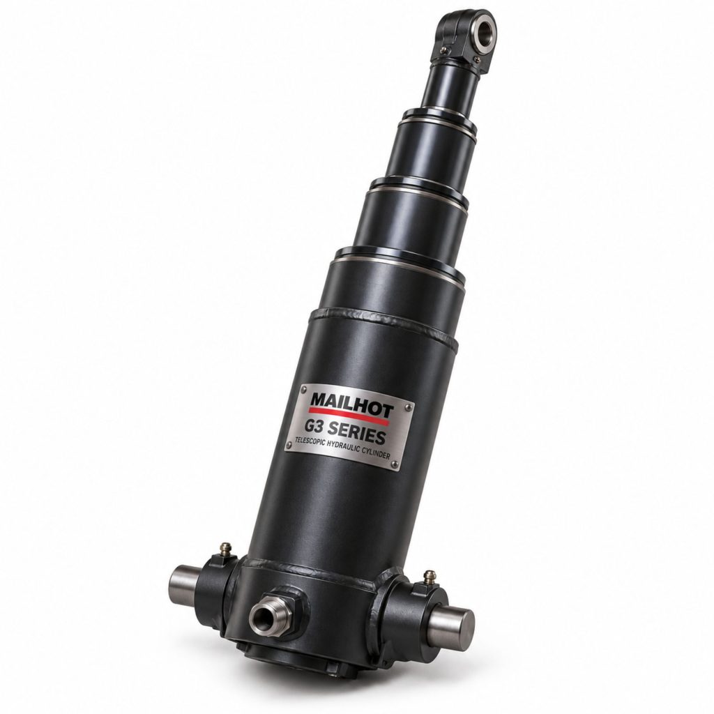
The Mailhot G3 is a heavy-duty telescopic hydraulic cylinder designed primarily for dump-body lifting and other vocational applications requiring a long working stroke from a relatively compact retracted package. Its nested cylinder stages extend sequentially as hydraulic pressure enters the assembly, raising the dump body through its designed tipping arc.
Mailhot describes the G3 as a trunnion-mounted telescopic cylinder with a protective cover and a high capacity-to-speed ratio. The trunnion mounting allows the cylinder to pivot as the body rises, while the cover protects the hydraulic connection area and helps produce a compact installation.
The G3 family includes application-specific configurations with different strokes, stage counts, closed lengths, oil requirements, mounting dimensions, and lifting characteristics. Cylinder selection must be based on the complete hoist geometry and vehicle application rather than stroke or nominal body length alone.
Key Characteristics
- Multi-stage telescopic hydraulic construction
- Trunnion-mounted cylinder design
- Protective cover around the connection area
- Compact closed length relative to available working stroke
- Model-specific three- and four-stage configurations
- Working pressure up to 2,750 psi on published configurations
- Nitrided cylinder surfaces for wear and corrosion resistance
- Designed for harsh vocational operating conditions
- Application-specific stroke, oil volume, weight, and mounting dimensions
- Suitable for properly engineered dump-truck and trailer hoist systems
Major Components
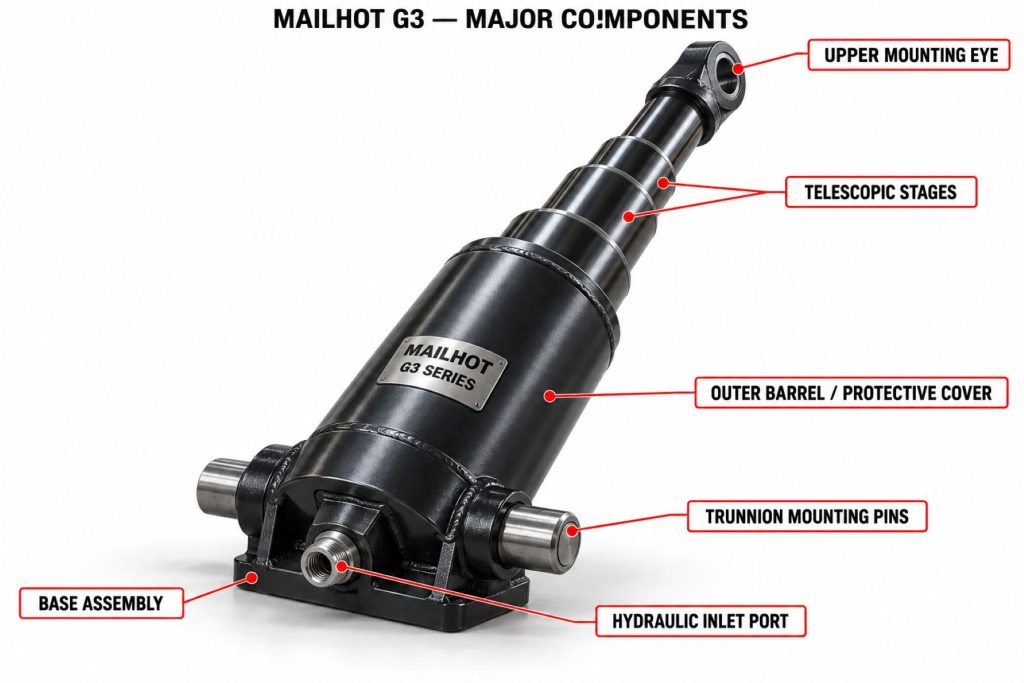
- Outer barrel
- Nested telescopic stages
- Plunger or final moving stage
- Trunnion mounting assembly
- Protective connection cover
- Hydraulic inlet port
- Stage guides and bearings
- Hydraulic seals
- Wiper seals
- Wear rings
- Internal retaining components
- Breather or venting provisions where specified
- Mounting pins, retainers, and brackets
- Hydraulic hose and fitting connection
Product Type and Construction
The G3 is a telescopic cylinder constructed with multiple tubular stages nested inside one another. This architecture provides substantially more extension than a conventional single-stage cylinder of a similar closed length.
Published G3 models include different barrel families, strokes, and numbers of stages. The model designation generally communicates important dimensional information, but the full Mailhot model and part number must be used for positive identification.
Mailhot uses a nitriding treatment intended to harden the cylinder surfaces and improve resistance to abrasion and corrosion. The protective qualities of the cylinder still depend on correct installation, clean hydraulic oil, regular inspection, and protection from damaging side loads.
How the Telescopic Hydraulic Cylinder Works
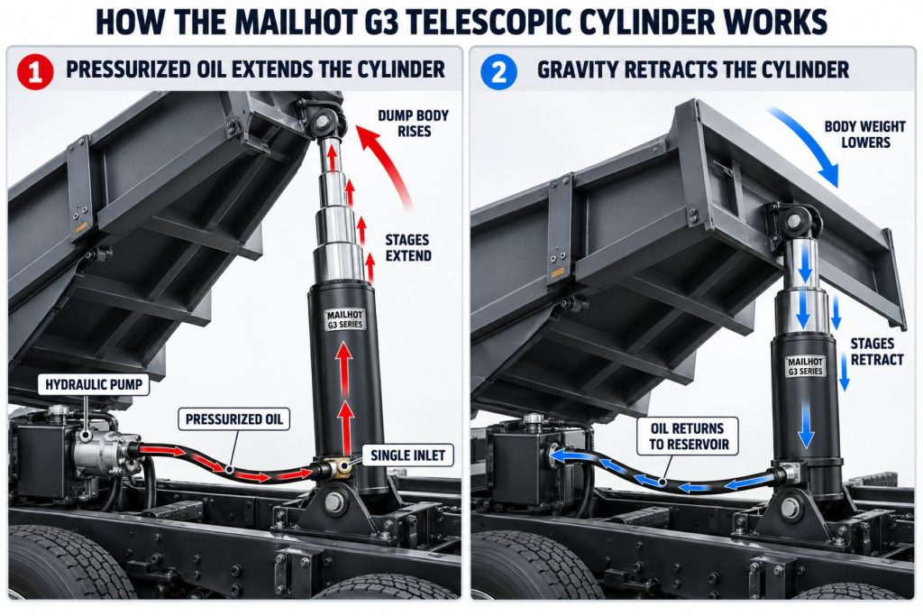
When the operator activates the hoist control, the power take-off drives the hydraulic pump. Oil travels from the reservoir through the control valve and hydraulic hose to the G3 cylinder.
Hydraulic pressure acts on the cylinder’s internal effective area. The largest moving stage normally extends first, followed by progressively smaller stages. This sequential movement lengthens the cylinder and raises the front of the dump body.
When the control is moved to the lowering position, the valve provides a return path to the reservoir. The weight of the dump body retracts the single-acting cylinder and forces oil back through the hydraulic circuit. Lowering speed must remain controlled and within the body, valve, and cylinder manufacturers’ requirements.
Position and Function Within the Vehicle
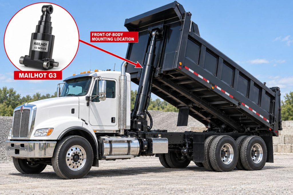
The G3 is commonly installed near the front of a dump body, usually behind the cab or toward the forward portion of a dump trailer. Its trunnions pivot in matching support brackets as the body moves through its tipping arc.
The cylinder converts hydraulic pressure and flow into linear lifting movement. It is not intended to serve as a permanent structural support for a raised body. Approved body-prop or blocking procedures must be used before anyone works beneath an elevated dump body.
Common Specifications
- Cylinder Type: Telescopic dump-hoist cylinder
- Action: Commonly single-acting
- Mounting: Trunnion-mounted with protective cover
- Stage Count: Model-specific, commonly three or four
- Published Working Pressure: Up to 2,750 psi on representative G3 models
- Stroke: Model-specific; published configurations cover multiple dump-body requirements
- Oil Volume: Varies by stroke, barrel family, and number of stages
- Hydraulic Port: Model-specific SAE connection
- Surface Protection: Nitrided cylinder components
- Retraction: Gravity-powered through the weight of the body
- Hydraulic Supply: Properly matched PTO, pump, reservoir, valve, hose, fittings, and filtration
- Installation: Application-engineered according to body length, hinge position, mounting geometry, and required tipping capacity
Stroke, Stage Count, and Operating Capacity
G3 capacity depends on the cylinder model, hydraulic pressure, mounting position, dump-body geometry, load distribution, and angle through which the cylinder applies force. A cylinder capable of producing a high theoretical force can still be unsuitable if its stroke, closed length, extended length, or mounting geometry does not match the body.
Representative published G3 five-inch models include three-stage configurations with nominal strokes around 100 to 130 inches and working pressure ratings of 2,750 psi. Larger model families and four-stage configurations are used where longer extension is required. The applicable Mailhot specification sheet must be consulted for exact dimensions, oil volume, weight, and pressure limits.
The cylinder must never be selected solely by truck size or dump-body length. The body manufacturer or hoist engineer should confirm the required tipping force, mounting location, initial lift angle, maximum body angle, hinge geometry, load center, and structural requirements.
Hydraulic Pressure, Flow, and Cycle Speed
Hydraulic pressure determines the force available from the cylinder, while pump flow affects extension speed. Raising pressure above the cylinder or system rating is not an acceptable way to compensate for an undersized cylinder or an overloaded body.
Excessive flow can cause overly rapid stage movement, harsh transitions, heat, foaming, and loss of operating control. Insufficient flow can make the hoist unreasonably slow. The pump displacement, engine or PTO speed, valve capacity, hose size, and reservoir configuration must be matched to the selected G3 model.
Hydraulic Circuit and System Integration
A typical G3 installation operates as part of a complete wet-line or dump-hoist hydraulic circuit containing:
- Transmission-mounted power take-off
- Hydraulic pump
- Hydraulic reservoir
- Directional control valve
- Pressure-relief protection
- Supply and return hoses
- Hydraulic fittings
- Breather and filtration components
- In-cab, air, cable, electric, or electronic controls
- Mailhot G3 telescopic cylinder
Every component must have adequate pressure, flow, temperature, and oil compatibility ratings. Restrictions in the return circuit can increase lowering pressure and heat, while contamination can damage seals, guides, and precision cylinder surfaces.
Controls and Operating Functions
The cylinder is normally controlled through a raise, hold, and lower valve. The operator may control the system with a lever, cable, air control, electrical switch, or electronic interface, depending on the wet kit and body installation.
A correctly configured hold position stops normal oil movement and maintains body position temporarily. The cylinder must not be treated as a safety support, even when the valve is in hold. Hydraulic leakage, hose failure, valve movement, or internal bypass can allow the body to descend.
Mounting and Installation
The G3 trunnions must be installed in correctly aligned brackets that allow the cylinder to pivot freely throughout the complete lifting and lowering cycle. The hydraulic connection, cover, stages, and surrounding structure require adequate clearance in every operating position.
The installation must preserve the body manufacturer’s specified relationship between the cylinder, body hinge, subframe, crossmembers, and load center. Incorrect geometry can reduce initial lifting force, overload the cylinder, create side loading, or allow the cylinder to reach full extension before the body reaches its intended angle.
Hydraulic hoses should be routed to prevent stretching, pinching, twisting, heat exposure, and abrasion as the cylinder pivots. Installation and welding procedures must follow Mailhot, body-manufacturer, chassis-manufacturer, and qualified upfitter requirements.
Vehicle Frame and Body Compatibility
Compatibility depends on the complete vehicle and body installation, including:
- Truck or trailer frame strength
- Dump-body length and construction
- Body hinge location
- Subframe and crossmember design
- Available closed-cylinder space
- Required extended length and dump angle
- Trunnion bracket position
- Hydraulic system pressure and flow
- Reservoir capacity
- Payload and load-center location
- Cab, exhaust, driveline, and equipment clearance
- Vehicle gross and axle weight ratings
A G3 cylinder should not be substituted for another model merely because the stroke appears similar. Differences in closed length, extended length, barrel diameter, trunnion location, port arrangement, stage sequence, and rated pressure can make an otherwise similar cylinder incompatible.
Common Applications
- Municipal dump trucks
- Construction dump trucks
- Severe-service dump trucks
- Dump trailers
- Transfer trailers
- Refuse trucks
- Vacuum trucks and trailers
- Snow and ice-control vehicles
- Aggregate-hauling equipment
- Asphalt and paving-support vehicles
- Specialized tilting-body equipment
Advantages
- Long working stroke from a compact retracted package
- Trunnion mounting accommodates the changing dump-body angle
- Protective cover shields the hydraulic connection area
- Multiple models support different body and stroke requirements
- High capacity-to-speed design for vocational lifting applications
- Nitrided surfaces support durability in demanding environments
- Single-acting operation simplifies a typical dump-hoist circuit
- Established use in truck, trailer, refuse, and vocational equipment
- Manufacturer parts, specifications, and support resources are available
Limitations or Considerations
- Requires application-specific engineering and mounting geometry
- Must not be exposed to excessive side loading
- Hydraulic contamination can shorten seal and stage life
- Incorrect pressure or flow can damage the cylinder and body system
- Gravity retraction depends on proper body weight and unrestricted oil return
- A raised body requires an approved mechanical support before service
- Model numbers with similar strokes may not be interchangeable
- Cold-weather oil viscosity can slow operation
- Uneven ground or a poorly distributed load can increase rollover risk
- Winter road-maintenance use may affect applicable warranty coverage
Driver and Operator Experience
A correctly matched G3 cylinder should raise the body smoothly through its operating range. The operator may notice stage transitions as the effective cylinder area changes, but violent movement, severe vibration, binding, or unexpected speed changes require inspection.
Before raising the body, the operator should confirm that the vehicle is on firm, reasonably level ground, the load is distributed properly, overhead clearance is available, and the rear discharge area is clear. The operator should monitor the truck, trailer, body, and load throughout the cycle and stop immediately if the vehicle begins leaning or the load fails to release evenly.
Operating Procedure
A general operating sequence includes the following steps. The vehicle, body, PTO, pump, valve, and cylinder manufacturers’ instructions always take priority.
- Park on firm and stable ground and apply the parking brake.
- Check overhead, side, and rear clearance.
- Confirm that the load is suitable and evenly distributed.
- Engage the PTO according to the transmission and PTO instructions.
- Operate the raise control while monitoring the body and vehicle.
- Stop immediately if the body leans, binds, or moves abnormally.
- Discharge the load without exceeding the approved body angle or cylinder travel.
- Move the control to lower and allow the body to descend smoothly.
- Confirm that the body is fully seated.
- Return the valve to neutral and disengage the PTO before driving.
Inspection and Wear Points
- Telescopic stages for scoring, dents, corrosion, or contamination
- Stage seals and wipers for leakage or damage
- Outer barrel for distortion or impact damage
- Trunnions and mounting brackets for wear or cracking
- Mounting pins and retainers for movement or damage
- Protective cover and hydraulic connection area
- Hydraulic hose for abrasion, cracking, or blistering
- Fittings and port connection for leakage
- Body hinge and subframe condition
- Crossmembers and mounting structure
- Hydraulic reservoir oil level and condition
- Control valve, relief valve, and pump operation
Lubrication Requirements
Use the hydraulic-fluid type and viscosity specified for the complete system and expected operating temperature. Mixing incompatible fluids can damage seals, reduce lubrication, increase foaming, or change cold-weather performance.
External mounting pins, body hinges, and other grease points should be lubricated according to the body and equipment manufacturers’ schedules. Do not apply unapproved grease or coatings to exposed telescopic stages because they can collect abrasive contamination and interfere with the wipers and seals.
Maintenance and Ownership Notes
Routine maintenance should include checking hydraulic-fluid level and condition, inspecting the telescopic stages, looking for external leakage, confirming secure mounting hardware, and examining the complete body-hoist structure.
Keep the hydraulic system sealed and clean during hose, valve, pump, or cylinder service. Replacement oil should meet the equipment manufacturer’s requirements, and filters and reservoir breathers should be serviced at their prescribed intervals.
Mailhot warranty terms depend on the product, application, installation, and operating conditions. Mailhot states that G2 and G3 warranty coverage is reduced for equipment used in winter road maintenance involving salt or liquid ice-melting chemicals. Current written warranty terms should be reviewed for the exact installation.
Common Hydraulic Cylinder Problems
- Cylinder will not extend: A disengaged PTO, low reservoir level, failed pump, incorrect valve position, blocked line, excessive load, or internal hydraulic failure may prevent operation.
- Slow or uneven extension: Low pump flow, cold oil, air in the system, restricted hoses, contamination, worn components, or binding caused by side loading may be responsible.
- Cylinder will not retract: A restricted return line, valve malfunction, mechanical interference, damaged stage, improper body geometry, or insufficient body weight can prevent normal gravity retraction.
- External oil leakage: Damaged seals, scored stages, loose fittings, cracked hoses, or impact damage may allow hydraulic oil to escape.
- Body drifts downward: Internal cylinder bypass, control-valve leakage, damaged plumbing, or an external leak may allow the body to descend.
- Stages extend out of sequence: Contamination, internal wear, damaged surfaces, excessive side load, or unsuitable oil can disrupt normal telescopic movement.
- Cylinder bends or binds: Misaligned trunnion brackets, body distortion, a damaged hinge, uneven loading, or operation on unstable ground can impose damaging lateral forces.
- Hydraulic system overheats: Excessive pump speed, prolonged relief-valve operation, restricted lines, undersized components, contaminated oil, or an improperly selected circuit may generate excessive heat.
Safety and Service Precautions
- Never work beneath a raised body supported only by hydraulic pressure.
- Use the approved body prop or blocking system before inspection or repair.
- Relieve hydraulic pressure before disconnecting a hose, fitting, valve, or cylinder.
- Keep people clear of the body, tailgate, cylinder, hinges, and pinch points.
- Do not search for hydraulic leaks with bare hands.
- Treat fluid-injection injuries as medical emergencies.
- Do not exceed the cylinder or hydraulic system pressure rating.
- Do not operate with bent, scored, leaking, or misaligned cylinder components.
- Avoid raising a loaded body on soft, uneven, or severely sloped ground.
- Do not move the vehicle with the body raised unless an approved procedure specifically permits it.
- Use lifting equipment capable of safely supporting removed cylinder components.
- Follow lockout, tagout, and stored-energy procedures during service.
Identification Information
Record the complete information from the Mailhot identification plate or marking before ordering parts or a replacement cylinder:
- G3 model designation
- Complete Mailhot part number
- Serial number
- Nominal stroke
- Number of telescopic stages
- Barrel or model family
- Closed and extended dimensions
- Working-pressure rating
- Hydraulic-port size and location
- Trunnion location and mounting dimensions
- Truck, trailer, and body manufacturer
- Body length and hinge arrangement
- Original equipment build information
Do not identify the cylinder by appearance alone. Several Mailhot configurations can look similar while using different dimensions, stages, mount locations, oil volumes, or pressure ratings.
Buying Considerations
- Confirm the complete G3 model, part number, and serial number.
- Verify the required stroke and closed length.
- Confirm the number of telescopic stages.
- Match the trunnion position and mounting dimensions.
- Verify the hydraulic-port size and orientation.
- Confirm the permitted working pressure.
- Check required oil volume and reservoir capacity.
- Match the cylinder to the body length and hinge geometry.
- Confirm initial tipping force and maximum body angle.
- Inspect the frame, subframe, crossmembers, hinges, and brackets.
- Review PTO, pump, valve, hose, and filtration compatibility.
- Confirm parts, seal-kit, and authorized service availability.
- Review current Mailhot warranty requirements.
- Use a qualified truck-equipment installer for replacement or conversion work.
Variants and Configurations
- Different nominal stroke lengths
- Three-stage configurations
- Four-stage configurations
- Different barrel-diameter families
- Different closed and extended lengths
- Different oil-volume requirements
- Different cylinder weights
- Application-specific trunnion locations
- Different hydraulic-port arrangements
- Dump-truck configurations
- Dump-trailer configurations
- Refuse and specialized vocational configurations
Published examples include G3 model designations such as G3 100-5-3, G3 110-5-3, G3 120-5-3, and G3 130-5-3. Other configurations use different stroke, barrel, and stage designations. Availability and supersession information should be verified directly with Mailhot Industries.
Comparison to Similar Equipment
Compared with the Hyva Alpha Series Front-End Cylinder, the Mailhot G3 uses Mailhot’s application-specific trunnion mounting, protective cover, model structure, and nitrided construction. Neither product should be substituted without confirming the complete mounting and operating specifications.
Compared with the planned Custom Hoists 500 Series Underbody Hoist, the G3 is a front-mounted telescopic cylinder. An underbody hoist applies lifting force beneath the body through a different linkage and mounting arrangement.
Compared with a conventional single-stage hydraulic cylinder, the G3 provides substantially greater working travel relative to its retracted length. Its multi-stage design also introduces additional sealing, guiding, inspection, and alignment requirements.
Best Fit For
- Vehicles originally engineered for a Mailhot G3 cylinder
- Dump trucks requiring a compact front-mounted hoist
- Dump trailers requiring long telescopic extension
- Municipal and construction fleets
- Severe-duty vocational vehicles
- Refuse and vacuum equipment using compatible mounting geometry
- Applications requiring a trunnion-mounted cylinder with a protective cover
- Operators with access to qualified hydraulic service and replacement support
Related Vehicle and Trailer Types
- Commercial Trucks
- Dump Trailers
- End Dump Trailers
- Refuse Trucks
- Vacuum Trucks
- Vocational Trucks
- Municipal Trucks
Related Truck and Trailer Models
- Mack Granite
- Kenworth T880
- Peterbilt 567
- Freightliner 114SD
- International HX Series
- Western Star 47X
- Western Star 49X
- Volvo VHD
Related PTO and Hydraulic System Types
- Power Take-Off Systems
- Hydraulic Pumps & Motors
- Wet Kits & Complete Hydraulic Systems
- Hydraulic Cylinders & Dump Hoists
- Hydraulic Valves, Controls & Reservoirs
- Hydraulic Hoses, Fittings & Filtration
Related PTO and Hydraulic Products
- Hyva Alpha Series Front-End Cylinder
- Custom Hoists 500 Series Underbody Hoist
- Permco DM-640 Dump Pump
- Permco P5151 Hydraulic Pump
- Parker F1 Hydraulic Pump
- Parker F2 Twin-Flow Hydraulic Pump
- Muncie E Series Hydraulic Pump
- Muncie V Series Hydraulic Directional Control Valve
- Muncie WETLINE Hydraulic System
- Parker Chelsea Wetline Hydraulic System
Related Equipment Systems
- PTO & Hydraulic Systems
- Transmissions
- Suspension Systems
- Axles & Differentials
- Brake Systems
- Electrical Systems
- Tires & Wheels
Related Guides
- PTO & Hydraulic System Guides
- How Commercial Truck PTO and Hydraulic Systems Work
- Commercial Truck Power Take-Off Types Explained
- How to Choose a PTO and Hydraulic Pump
- Commercial Truck Wet Kits Explained
- How to Inspect and Maintain Truck Hydraulic Systems
- How Dump Truck Hydraulic Systems Work
- Front-End Cylinder vs Underbody Hoist
- How to Select a Dump Truck Hydraulic Cylinder
Regulatory and Compliance Notes
Installing a G3 cylinder does not increase the truck or trailer’s certified gross vehicle weight rating, axle ratings, frame rating, tire capacity, wheel capacity, or legal payload. The completed vehicle remains limited by its certification and lowest-rated component.
Installation must preserve required lighting, conspicuity, braking, stability, exhaust, fuel-system, electrical, and clearance requirements. Hydraulic hoses and equipment must be routed and protected according to applicable vehicle, body, hydraulic-component, and workplace-safety standards.
Final-stage manufacturers and upfitters are responsible for ensuring that modifications comply with applicable federal, state, provincial, and local requirements. Inspection and operating rules can vary by jurisdiction and type of vocational equipment.
Real World Operating Notes
Dump-body instability is frequently influenced by ground conditions and load behavior rather than cylinder force alone. Frozen, wet, or unevenly distributed material can remain inside one side of the body and move the center of gravity away from the vehicle centerline.
A cylinder that operates normally while empty may still bind or expose an installation problem under load. Any leaning, twisting, stage scoring, bracket movement, or abnormal noise should be investigated before the vehicle returns to service.
Cold hydraulic oil increases resistance and can slow the first operating cycles. Operators should follow the wet-kit manufacturer’s cold-weather procedures instead of increasing engine speed or relief pressure to force faster movement.
Frequently Asked Questions
What is the Mailhot G3?
The Mailhot G3 is a trunnion-mounted, multi-stage telescopic hydraulic cylinder designed for dump bodies and other demanding vocational lifting applications.
Is the G3 a single-acting cylinder?
Common G3 dump-hoist configurations are single-acting. Hydraulic pressure extends the cylinder, and the weight of the body retracts it while oil returns to the reservoir.
What is the G3 working-pressure rating?
Published G3 specification information identifies working pressures up to 2,750 psi on representative configurations. The rating on the exact cylinder identification and specification sheet must be followed.
How many stages does a G3 cylinder have?
The number depends on the model. Common published configurations include three-stage and four-stage cylinders.
What does trunnion-mounted mean?
Trunnions are projecting pivots on the cylinder assembly that fit into matching mounting brackets. They allow the cylinder to rotate as the dump body rises and lowers.
Can a G3 cylinder replace another Mailhot model?
Only when Mailhot or a qualified body-hoist specialist confirms compatibility. Stroke, closed length, extended length, trunnion location, hydraulic port, stage count, pressure rating, and lifting geometry must all match.
Why does a telescopic cylinder leak between stages?
Possible causes include damaged seals, scored stages, contamination, corrosion, excessive side loading, worn guides, or operation beyond the cylinder’s limits.
Can someone work beneath a body held up by the G3 cylinder?
No. A raised body must be secured with the approved mechanical body prop or blocking system before anyone enters the hazardous area beneath it.
Does the G3 require special hydraulic oil?
The oil must meet the specifications established for the complete hydraulic system and operating climate. The pump, valve, seals, hoses, and cylinder must all be compatible with the selected fluid.
How is the correct G3 replacement identified?
Use the complete Mailhot model, part number, serial number, stroke, stage count, mounting dimensions, port arrangement, and original vehicle or body build information.
Availability and Where to Find
Mailhot G3 cylinders, replacement components, technical specifications, and service support may be available through Mailhot Industries, authorized hydraulic distributors, truck-equipment dealers, dump-body manufacturers, trailer manufacturers, and qualified hydraulic repair facilities.
Availability depends on the exact model, stroke, stage count, mounting dimensions, and application. Before ordering, provide the complete cylinder identification and confirm whether the original model remains current or has an approved replacement.
Current product information, technical assistance, warranty details, and manufacturer contact resources are available through the Mailhot Industries website.
Support Trucking Families
Truck Equipment Atlas supports the mission of Grey Cross, a nonprofit dedicated to helping families of truck drivers who lose their lives while on the road. As the site grows, part of its mission is to bring awareness and support to these families.
Podcast or Video Section
Learn More Through Audio and Video
Truck Equipment Atlas will continue expanding with podcast episodes, interviews, and equipment breakdowns to help drivers and fleets better understand trucks and equipment.
Follow the Growth of Truck Equipment Atlas
Truck Equipment Atlas continues to expand with new truck profiles, trailer coverage, diesel engine pages, equipment system resources, manufacturer information, and educational guides.
Visit our Site Updates page to explore recent additions, project milestones, and upcoming resources as we continue building one of the industry’s growing commercial trucking equipment reference libraries.
View the Latest Site Updates: Truck Equipment Atlas Site Updates