
Quick Facts
- Manufacturer: Muncie Power Products
- Product Series: CS6 Series
- Product Type: Clutch-shift power take-off
- Mounting Pattern: SAE six-bolt transmission opening
- Compatible Transmissions: Application-specific Allison and Aisin automatic transmissions and selected manual transmissions
- Maximum Intermittent Torque: Up to 300 lb-ft, depending on ratio and transmission application
- Maximum Continuous Torque: Up to 210 lb-ft, depending on ratio and application
- Maximum Intermittent Power: Up to 57 horsepower at 1,000 PTO rpm, depending on ratio
- Speed Ratios: Multiple application-specific ratios, including 03, 04, 05, 06, 07, 09, and 12 configurations
- Pump-Mounting Options: SAE A, SAE B, SAE BB, and DIN 5462 direct-mount configurations
- Remote Outputs: Keyed and flange-type output-shaft options
- Primary Applications: Dump, construction, refuse, snow and ice, towing, recovery, and utility equipment
- Production Status: Current product family; exact configurations depend on transmission application
Overview
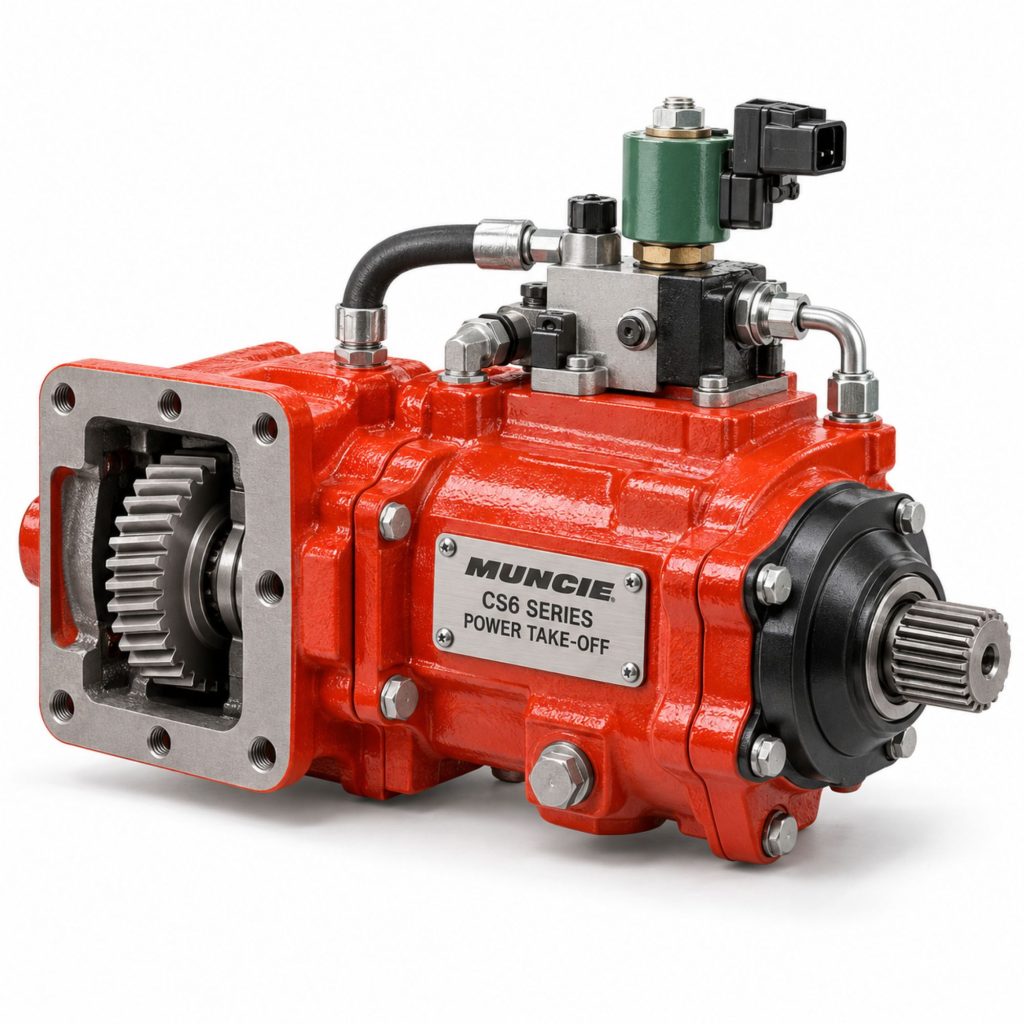
The Muncie CS6 Series is a six-bolt, clutch-shift power take-off designed to transfer power from a commercial vehicle transmission to a hydraulic pump or another piece of auxiliary equipment. It is used on vocational trucks that require dependable engagement, substantial torque capacity, and compatibility with automatic or manual transmissions.
The CS6 is commonly paired with Allison 1000 and 2000 Series automatic transmissions, although application-specific versions are available for selected Aisin automatics and current manual transmissions. The transmission model, PTO opening, input gear, rotation, speed ratio, shift system, output, and lubrication requirements must all be confirmed before a unit is ordered.
A hydraulically applied internal clutch allows the PTO to engage without relying on a sliding mechanical gear. Muncie’s patented drag brake is standard and helps prevent unwanted output-shaft rotation while the PTO is disengaged. An upgraded multidisc clutch-brake configuration may be available when the application requires more complete shaft stoppage.
Direct-mount pump flanges and remote-drive outputs allow the CS6 to support dump pumps, hydraulic gear pumps, piston pumps, blowers, compressors, generators, and other vocational equipment when properly specified.
Key Characteristics
- Six-bolt, transmission-mounted power take-off
- Clutch-shift engagement system
- Compatible with selected automatic and manual transmissions
- Patented Muncie drag brake supplied as a standard feature
- Optional upgraded clutch brake for applications requiring stronger shaft stopping
- Multiple transmission input gears and speed ratios
- Direct-mount and remote-drive output configurations
- Rotatable direct-mount pump flanges
- Application-specific electric, hydraulic, pneumatic, and electronic controls
- Pressure-lubricated configurations for applicable transmissions
- Designed for medium-duty and heavy-duty vocational equipment
- Available in configurations for high-torque and high-horsepower hydraulic applications
Major Components
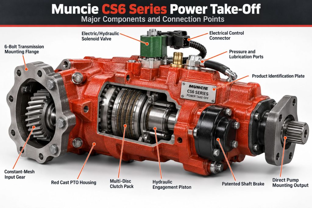
- PTO housing
- Transmission input gear
- Drive gear and internal gear train
- Multidisc clutch pack
- Output shaft
- Output-shaft bearings
- Drag-brake assembly
- Shift piston
- Return springs
- Hydraulic or pneumatic activation components
- Solenoid valve where specified
- Pressure switch
- Direct-mount pump flange or remote output
- Mounting studs and fasteners
- Gaskets and seals
- Pressure-lubrication fittings where required
- Electrical harness and operator controls where equipped
Product Type and Construction
The CS6 is a side-mounted, six-bolt PTO using an internal clutch pack to connect the transmission-driven input gear to the output assembly. This arrangement differs from a conventional mechanically shifted PTO in which a sliding gear is physically moved into engagement.
Its housing contains the gear train, clutch pack, bearings, seals, output assembly, and engagement components. The exact construction varies with the selected assembly arrangement, transmission gear, ratio, shift type, output option, and special-feature code.
The modular design permits the PTO to be configured for a direct-mounted hydraulic pump or a remote-driven component. Rotatable pump flanges can help position a direct-mounted pump around frame rails, exhaust equipment, transmission components, and other chassis restrictions.
How the Power Take-Off Works
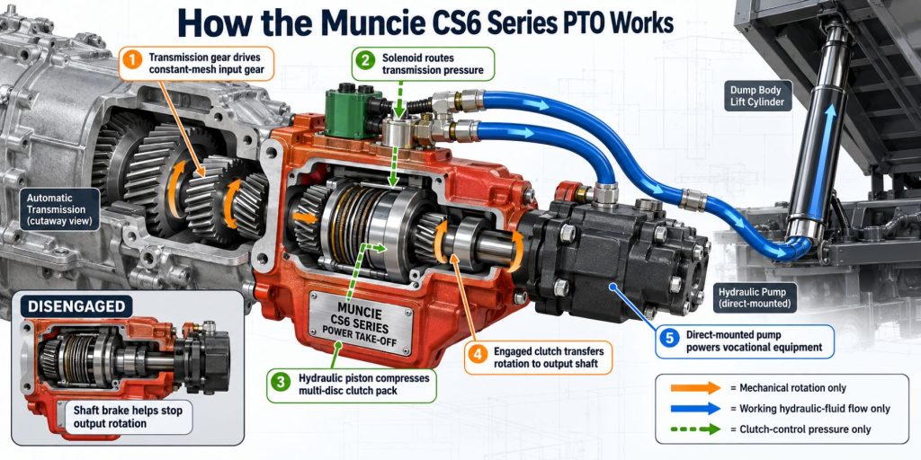
A transmission gear drives the CS6 input gear whenever the applicable transmission power path is rotating. With the PTO disengaged, the clutch pack does not transfer usable torque to the output shaft, and the drag brake helps limit residual shaft rotation.
When the operator activates the approved PTO control, the engagement system applies pressure to an internal piston. The piston compresses the clutch pack, connecting the rotating input section to the PTO output. The output then powers a directly mounted hydraulic pump or transfers power through a driveshaft to remote equipment.
When the PTO is switched off, engagement pressure is released and the clutch pack separates. The drag brake helps slow or stop the unloaded output assembly. Operating behavior varies by transmission, control programming, vehicle speed, engine speed, and driven-equipment configuration.
Position and Function Within the Vehicle
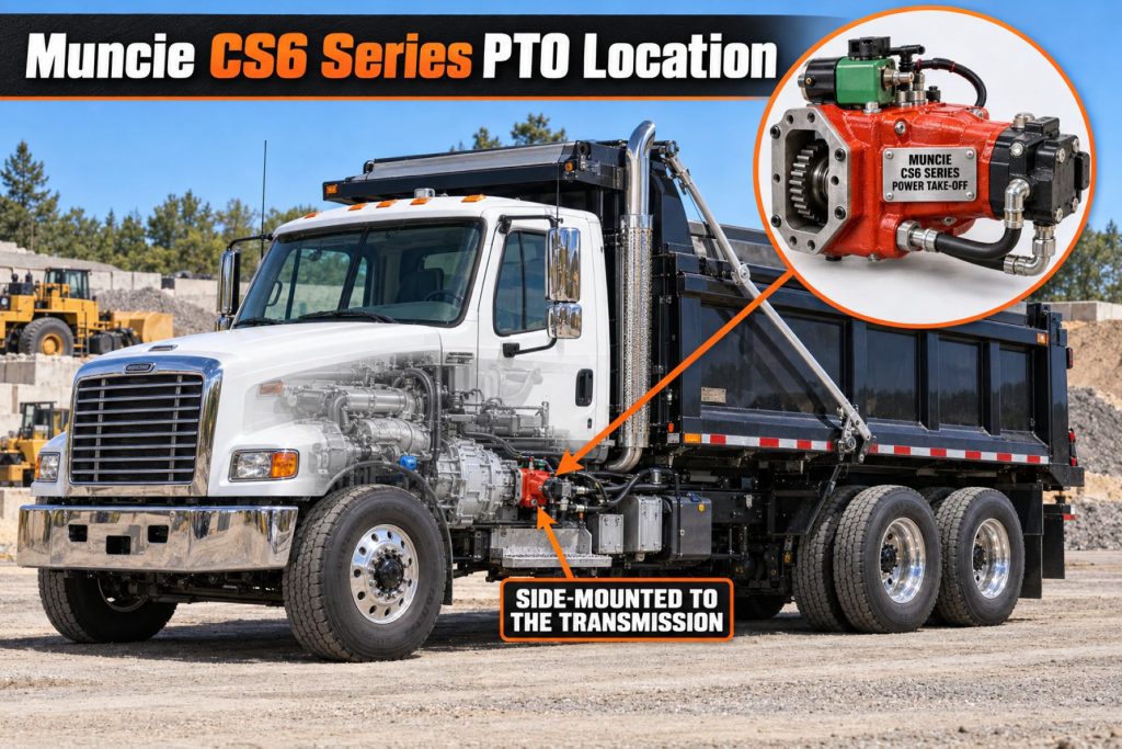
The CS6 mounts to an approved six-bolt PTO opening on the vehicle transmission. Depending on the transmission and chassis, the available opening may be on the driver or passenger side.
Its function is to divert a controlled portion of engine and transmission power to vocational equipment. Common driven systems include hydraulic pumps for dump bodies, refuse equipment, cranes, recovery equipment, snowplows, spreaders, aerial devices, and utility machinery.
The PTO does not create power. Its available output depends on engine speed, transmission gearing, PTO ratio, clutch capacity, lubrication, and the limitations of every component in the driven system.
Common Specifications
- Mounting configuration: SAE six-bolt transmission opening.
- Engagement design: Clutch-shift PTO with an internal multidisc clutch pack.
- Standard shaft control: Patented Muncie drag brake.
- Published speed-ratio codes: 03, 04, 05, 06, 07, 09, and 12, subject to transmission compatibility.
- Maximum intermittent torque for ratios 03 through 07: 300 lb-ft.
- Maximum continuous torque for ratios 03 through 07: 210 lb-ft.
- Maximum intermittent power for ratios 03 through 07: 57 horsepower at 1,000 PTO rpm.
- Maximum intermittent torque for ratios 09 and 12: 275 lb-ft.
- Maximum continuous torque for ratios 09 and 12: 193 lb-ft.
- Maximum intermittent power for ratios 09 and 12: 52 horsepower at 1,000 PTO rpm.
- Direct-mount pump interfaces: SAE A, SAE B, SAE BB, and DIN 5462 options.
- Remote-drive outputs: Application-specific keyed-shaft and flange configurations.
- Approximate published weight: 47 to 49 pounds, depending on configuration.
All ratings must be verified for the complete PTO model number, transmission, ratio, operating speed, duty cycle, output, pump, and vehicle installation.
Power, Torque, Speed, and Operating Capacity
The published capacity of a CS6 varies by speed ratio. Ratios 03 through 07 may be rated for as much as 300 lb-ft of intermittent torque, 210 lb-ft of continuous torque, and 57 horsepower at 1,000 PTO rpm. Ratios 09 and 12 may be rated for as much as 275 lb-ft intermittently, 193 lb-ft continuously, and 52 horsepower at 1,000 PTO rpm.
These figures are PTO ratings rather than permission to operate every configuration at the maximum value. Actual allowable output may be reduced by the transmission gear, input gear, pump shaft, mounting flange, driveshaft, hydraulic pressure, operating speed, or vehicle manufacturer’s limits.
PTO output speed is determined by the transmission’s PTO drive gear, the selected CS6 ratio, and engine speed. The correct ratio should allow the pump or driven component to reach its required speed without excessive engine rpm or overspeeding the equipment.
Intended Transmission and Mounting Position
The CS6 is intended for transmissions equipped with a compatible six-bolt PTO aperture and approved internal drive gear. Applications include selected Allison and Aisin automatics as well as certain manual transmissions.
On Allison 1000 and 2000 RDS applications, the correct CS6 configuration commonly uses the application-specific A67 input-gear family. Muncie specifies pressure lubrication for applicable CS6 installations on these transmissions.
The approved mounting side depends on the transmission, PTO opening, output rotation, available chassis clearance, and pump arrangement. A PTO should never be selected using the transmission manufacturer’s name alone.
PTO Engagement and Shift System
The CS6 uses clutch-shift engagement rather than a sliding mechanical gear. Available configurations may use electric-over-hydraulic, air, hydraulic, or vehicle-integrated controls, depending on the transmission and PTO model.
Some automatic-transmission applications use an integral solenoid configuration. This arrangement can simplify installation by placing the controlling solenoid on the PTO assembly, but the correct wiring, pressure supply, switches, and vehicle programming remain essential.
Engagement should occur only under the conditions authorized by Muncie, the transmission manufacturer, and the vehicle builder. Engine speed, transmission range, vehicle speed, brake status, and equipment interlocks may all affect whether engagement is permitted.
Power Transfer and Output Design
The CS6 transfers power through its transmission input gear, internal gearing, clutch pack, and output assembly. Output configurations support both direct-mounted hydraulic pumps and remotely mounted equipment.
Direct mounting reduces the number of external driveline components and can create a compact installation. Remote mounting may be more appropriate when the pump or driven accessory cannot be positioned beside the transmission.
Remote systems require the correct PTO output, companion flange or keyed shaft, driveshaft, guards, alignment, operating angles, and support. Driveshaft speed and critical-speed limitations must be evaluated before the vehicle is operated.
Drag Brake and Output-Shaft Control
The standard Muncie drag brake helps prevent unwanted output-shaft rotation while the CS6 is switched off. Residual rotation can occur because of oil drag and internal movement within the PTO or transmission.
The drag brake is not a vehicle brake and does not replace safe shutdown, lockout, guarding, or equipment-blocking procedures. Applications requiring more positive shaft stoppage may need an upgraded multidisc clutch-brake configuration.
Selection between the standard drag brake and an upgraded brake should be based on the driven equipment, residual rotational energy, operating environment, and manufacturer approval.
Hydraulic Circuit and Equipment Integration
When the CS6 drives a hydraulic pump, the PTO becomes the mechanical power source for the hydraulic circuit. Pump displacement, PTO speed, and engine speed determine theoretical flow, while system pressure and flow determine the power required from the PTO.
A complete installation may include:
- Hydraulic pump
- Reservoir
- Suction and return lines
- Pressure hose
- Directional-control valves
- Pressure-relief valve
- Return and pressure filtration
- Hydraulic cylinders or motors
- Temperature and pressure monitoring
- Operator controls and safety interlocks
The PTO, pump, hydraulic plumbing, and driven equipment must be engineered as one system. Excessive hydraulic pressure, restricted lines, incorrect pump rotation, or improper relief-valve settings can overload the CS6 even when its speed appears acceptable.
Housing, Shaft, Bearing, and Clutch Design
The CS6 housing supports the internal gear train, output shaft, bearings, clutch pack, engagement piston, and brake components. Correct bearing preload, shaft alignment, lubrication, and fastener torque are essential to reliable operation.
The multidisc clutch pack carries torque when the PTO is engaged. Repeated engagement at excessive speed, insufficient apply pressure, excessive driven load, or contaminated lubricant can create heat and accelerate clutch wear.
Output-shaft and flange configurations must match the pump or remote driveline. Adapters should not be used unless they are approved for the PTO, pump, torque, speed, and installation.
Controls and Electronic Integration
Modern CS6 installations may communicate with transmission and vehicle control systems through switches, relays, solenoids, pressure switches, body-builder circuits, or programmed PTO modes.
Available control functions may include:
- Cab-mounted PTO enable switch
- PTO-engaged indicator
- Engine-speed control
- Park or neutral interlock
- Parking-brake interlock
- Vehicle-speed restriction
- Transmission range interlock
- Remote throttle control
- Hydraulic-system enable control
- Body or equipment safety interlocks
The exact wiring and programming procedure depends on the vehicle, transmission, model year, engine controls, body-builder interface, and CS6 shift option.
Efficiency, Heat, and Lubrication
PTO efficiency is affected by gear mesh, bearing condition, clutch condition, lubricant temperature, alignment, and the load imposed by the driven equipment. Some heat generation is normal, but excessive temperature may indicate overloading, clutch slippage, insufficient lubrication, an incorrect installation, or a failing pump.
Pressure-lubricated CS6 configurations use transmission oil supplied to the PTO to maintain lubrication under demanding operating conditions. Muncie requires the appropriate pressure-lubrication option for CS6 installations on applicable Allison 1000 and 2000 RDS transmissions.
The transmission lubricant must meet the transmission manufacturer’s requirements. Incorrect fluid, a low fluid level, contamination, restricted fittings, or leaking lubrication lines can damage both the transmission and PTO.
Duty Cycle and Operating Conditions
The CS6 may be used in intermittent or continuous-duty applications when the selected model, ratio, transmission, lubrication system, pump, and operating speed are approved for that duty.
Intermittent ratings apply to operations in which the PTO carries load for limited periods and receives adequate cooling time. Continuous-duty operation requires the complete system to remain within its continuous torque, power, speed, lubrication, and temperature limits.
Cold weather increases hydraulic-fluid viscosity and starting torque. The vehicle, PTO, and hydraulic system should be allowed to warm according to manufacturer instructions before heavy operation in near-freezing or subfreezing conditions.
Mounting and Installation
Installation requires the correct PTO model, input gear, ratio, output, shift option, assembly arrangement, mounting hardware, gasket arrangement, and lubrication components. Clearance must be checked before final assembly.
The installer should verify:
- Transmission identity and serial information
- Approved six-bolt PTO opening
- Correct PTO input gear and rotation
- Proper gear backlash where applicable
- Mounting-stud and fastener requirements
- Correct gasket or spacer stack
- Pump weight and support requirements
- Frame, exhaust, driveline, and crossmember clearance
- Hydraulic-hose routing
- Electrical and control-system connections
- Pressure-lubrication plumbing where required
- Absence of interference throughout powertrain movement
Installation should follow the current Muncie instructions for the exact PTO and transmission combination.
Transmission and Vehicle Compatibility
CS6 compatibility depends on more than the transmission series. Model year, transmission model, serial number, PTO opening, internal drive gear, control strategy, chassis packaging, engine programming, and body equipment can change the required configuration.
The PTO should be selected using current Muncie application data or the company’s Mpower specification system. Vehicle and transmission build information should be confirmed before ordering.
A CS6 configured for one Allison, Aisin, or manual transmission should not be assumed to fit another transmission, even when both provide six-bolt openings.
Pump, Driveshaft, and Driven-Equipment Compatibility
A direct-mounted pump must have the correct mounting flange, pilot, shaft type, spline, rotation, displacement, speed limit, pressure rating, and input-torque capacity.
Remote-driven equipment requires a compatible output shaft or flange and a properly engineered driveline. Driveshaft length, operating angle, balance, guarding, slip travel, yoke phasing, and critical speed must be evaluated.
The driven equipment must not demand more torque or horsepower than the lowest-rated component in the system can safely transmit.
Hydraulic Fluid, Filtration, and Reservoir Compatibility
The hydraulic system should use fluid approved by the pump and equipment manufacturers. Viscosity must remain suitable across the vehicle’s expected operating-temperature range.
The reservoir must provide adequate fluid volume, air separation, cooling, and contamination control. Suction restrictions, undersized hoses, poor reservoir placement, or clogged filters can cause cavitation and increase the load imposed on the PTO.
Hydraulic fluid and the transmission lubricant serving the PTO are normally separate systems. Each must be maintained according to its own specifications.
Common Applications
- Dump trucks
- Municipal snowplows
- Salt and material spreaders
- Refuse trucks
- Utility trucks
- Aerial devices
- Service trucks
- Hydraulic cranes
- Tow trucks
- Recovery vehicles
- Roll-off trucks
- Hooklift trucks
- Construction vehicles
- Vacuum equipment
- Hydraulic winches
- Generators and compressors
Advantages
- Clutch-shift engagement
- Substantial torque capacity for vocational equipment
- Compatibility with selected automatic and manual transmissions
- Standard patented drag brake
- Multiple speed-ratio choices
- Direct-mount and remote-drive outputs
- Rotatable pump flanges for improved clearance
- Multiple shift and control configurations
- Pressure-lubricated options for demanding applications
- Broad range of vocational uses
- Current manufacturer support and service literature
- Integration with modern vehicle PTO controls
Limitations or Considerations
- Must be matched to the exact transmission
- Not every ratio is approved for every application
- Requires correct control and interlock integration
- Pressure lubrication is required in specified installations
- Improper pump sizing can overload the PTO
- Direct-mounted pumps may create chassis-clearance problems
- Remote drives require alignment and guarding
- Cold hydraulic fluid can sharply increase starting load
- Continuous-duty limits are lower than intermittent ratings
- Incorrect wiring or programming can prevent engagement
- Installation errors can damage the PTO and transmission
- Standard drag-brake performance may not suit every application
Driver and Operator Experience
A correctly installed CS6 provides controlled PTO engagement through a cab-mounted or equipment-mounted control. The driver may see an indicator confirming that the PTO command has been accepted or that hydraulic pressure is present.
Operators should understand the required transmission range, parking-brake position, engine speed, vehicle-speed limit, and equipment sequence. The permitted procedure may differ between stationary and mobile operations.
Unusual noise, delayed engagement, warning messages, clutch slippage, hydraulic overheating, or unexpected output rotation should be investigated before continued operation.
PTO Engagement and Operating Procedure
The operator should follow the vehicle, transmission, PTO, and equipment manufacturers’ procedures. A general operating sequence may include:
- Position the vehicle on a suitable surface and secure it as required.
- Place the transmission in the specified range or operating mode.
- Apply the parking brake when required.
- Allow the engine, transmission, PTO, and hydraulic system to warm in cold conditions.
- Reduce engine speed to the approved engagement range.
- Activate the PTO control.
- Confirm the PTO-engaged indicator and normal equipment response.
- Increase engine speed only within the approved operating range.
- Monitor temperature, pressure, sound, vibration, and equipment movement.
- Return the engine to the required speed before disengagement.
- Switch off the driven equipment and PTO using the approved controls.
- Confirm that the PTO has disengaged before leaving the vehicle or servicing equipment.
This overview does not replace the operating instructions for the specific vehicle and equipment.
Inspection and Wear Points
- PTO housing and mounting flange
- Mounting studs, nuts, and cap screws
- Gasket and sealing surfaces
- Output shaft and pump connection
- Clutch-pack operation
- Output-shaft bearings
- Drag-brake operation
- Pressure-lubrication hoses and fittings
- Solenoid and shift components
- Electrical harnesses and connectors
- Pressure switches and indicator circuits
- Hydraulic-pump mounting hardware
- Remote driveline and guards
- Hydraulic hoses and fittings
- Transmission-fluid level and condition
Lubrication Requirements
The CS6 normally receives lubrication from the transmission and from any application-specific pressure-lubrication circuit. The correct lubricant type and fluid level are determined by the transmission manufacturer.
Pressure-lubricated installations require correctly routed hoses, fittings, orifices, and return connections. Any leak or restriction can reduce oil delivery to the PTO.
Remote driveline joints and driven equipment may have separate lubrication schedules. Those points should not be overlooked simply because the PTO itself uses transmission lubricant.
Maintenance and Ownership Notes
Inspect the PTO regularly for lubricant leakage, loose fasteners, unusual noise, excessive heat, damaged wiring, and hydraulic-system problems. Mounting fasteners should be checked according to the installation and maintenance instructions.
Maintain the transmission fluid at the correct level and service it at the required interval. Pressure-lubrication fittings and lines should remain clean, secure, and unrestricted.
A pump that is binding, cavitating, or operating against excessive pressure can shorten PTO life. Hydraulic problems should be corrected before a replacement PTO is installed.
Service parts should be selected using the complete CS6 model and assembly information rather than appearance alone.
Common PTO and Hydraulic-System Problems
- PTO will not engage: Possible causes include insufficient activation pressure, faulty wiring, a failed solenoid, an open interlock, incorrect transmission programming, damaged clutch components, or an incompatible control configuration.
- PTO engages slowly: Low apply pressure, cold or contaminated fluid, a restriction, clutch wear, or a leaking piston seal may delay engagement.
- PTO slips under load: Excessive driven torque, inadequate clutch pressure, worn clutch discs, hydraulic overpressure, or a failing pump may cause slippage.
- Output shaft rotates while disengaged: Oil drag, incorrect brake operation, worn brake components, or an application requiring an upgraded clutch brake may be responsible.
- Excessive noise: Incorrect gear compatibility, worn bearings, damaged gears, improper installation, low lubricant level, driveline misalignment, or pump problems may create noise.
- Oil leakage: Damaged seals, loose fittings, worn sealing surfaces, excess pressure, or loose mounting hardware may allow transmission lubricant to escape.
- PTO overheats: Overloading, clutch slippage, excessive operating speed, inadequate lubrication, high transmission temperature, or a failing hydraulic pump may generate excessive heat.
- Hydraulic system operates too slowly: Incorrect PTO ratio, low engine speed, pump wear, suction restriction, low fluid level, internal leakage, or improper pump displacement may reduce flow.
- Hydraulic system operates too quickly: An excessive PTO ratio, high engine speed, or oversized pump may produce more flow than the equipment requires.
Safety and Service Precautions
Never install or service the PTO with the engine running. Remove the ignition key, secure the vehicle, chock the wheels, and prevent anyone from starting the vehicle while personnel are underneath it.
Any raised dump body, hoist, crane, compactor, or other equipment must be mechanically blocked before anyone works beneath it. Hydraulic pressure alone must never be trusted to support raised equipment.
Stay clear of rotating shafts, pumps, and driven equipment. Remote PTO drivelines require appropriate guards wherever personnel could be exposed.
Depressurize hydraulic circuits before disconnecting hoses or components. Escaping hydraulic fluid can penetrate skin and cause severe injury.
Identification Information
The PTO identification plate or model code provides the information needed to identify its configuration. Record the complete number before ordering a replacement unit or internal parts.
- Complete Muncie PTO model number
- PTO series
- Transmission input-gear code
- Speed-ratio code
- Shift-type code
- Assembly arrangement
- Output code
- Special-feature code
- Transmission manufacturer and model
- Transmission serial number
- Vehicle identification number
- Pump manufacturer and model
- Hydraulic-system pressure and flow requirements
CS6 units that appear similar may contain different gears, ratios, outputs, shift systems, lubrication provisions, and transmission-specific components.
Buying Considerations
- Confirm the complete transmission model and serial number.
- Verify that the transmission has an approved six-bolt PTO opening.
- Determine the required PTO rotation.
- Calculate the required pump or equipment speed.
- Calculate intermittent and continuous torque demand.
- Select the appropriate CS6 speed ratio.
- Choose a direct-mount or remote-drive output.
- Match the pump flange and shaft.
- Confirm the required shift and control system.
- Verify pressure-lubrication requirements.
- Check chassis and pump clearance.
- Review continuous-duty and temperature requirements.
- Confirm electrical and transmission programming needs.
- Include the correct installation kit, wiring, fittings, and controls.
- Use an experienced PTO and hydraulic-equipment installer.
Variants and Configurations
- Multiple transmission input gears
- Multiple speed ratios
- Different assembly arrangements
- Electric-over-hydraulic engagement
- Air-operated engagement
- Hydraulic engagement
- Integral-solenoid configurations
- Vehicle-integrated control configurations
- SAE A direct pump mount
- SAE B direct pump mount
- SAE BB direct pump mount
- DIN 5462 direct pump mount
- Keyed remote output shaft
- Flanged remote output
- Standard drag brake
- Upgraded clutch-brake configuration
- Pressure-lubricated configurations
Comparison to Similar Equipment
Compared with the Muncie TG Series Power Take-Off, the CS6 uses clutch-shift engagement and offers greater published torque capacity in many applications. The TG Series is a mechanically shifted PTO that may be preferred when a simpler cable, air, or lever-operated system is appropriate.
Compared with the future Muncie FR6Q Power Take-Off, the CS6 is a side-mounted six-bolt PTO for selected automatic and manual transmissions. The FR6Q is intended for specific rear-mounted transmission applications and uses different packaging and power-transfer arrangements.
Compared with the Parker Chelsea 280 Series Power Take-Off, the CS6 offers Muncie-specific gearing, outputs, clutch controls, and application coverage. Selection should be based on the transmission and driven-equipment requirements rather than brand alone.
Compared with the Parker Chelsea 590 Series Power Take-Off, the CS6 serves a different range of transmission applications and uses its own mounting, ratio, control, lubrication, and output configurations.
Best Fit For
- Vehicles with an approved six-bolt PTO opening
- Allison 1000 and 2000 RDS applications requiring a clutch-shift PTO
- Selected Aisin automatic-transmission applications
- Compatible manual-transmission applications
- Dump and construction trucks
- Refuse vehicles
- Snow and ice equipment
- Utility and service trucks
- Tow and recovery vehicles
- Hydraulic systems requiring direct-mounted pumps
- Applications requiring remote-drive outputs
- Vocational equipment needing substantial PTO torque
Related Vehicle and Trailer Types
- Complete Guide to Semi Truck Types
- Class 6 vs Class 7 vs Class 8 Trucks
- Dump Trucks
- Refuse Trucks
- Utility Trucks
- Tow Trucks
- Roll-Off Trucks
- Service Trucks
Related Truck and Trailer Models
- Freightliner M2 106
- Freightliner 114SD
- International CV Series
- International HX Series
- Kenworth T280
- Kenworth T880
- Peterbilt 536
- Peterbilt 567
- Mack Granite
- Volvo VHD
Related PTO and Hydraulic System Types
- Power Take-Off Systems
- Hydraulic Pumps & Motors
- Wet Kits & Complete Hydraulic Systems
- Hydraulic Cylinders & Dump Hoists
- Hydraulic Valves, Controls & Reservoirs
- Hydraulic Hoses, Fittings & Filtration
Related PTO and Hydraulic Products
- Muncie TG Series Power Take-Off
- Muncie FR6Q Power Take-Off
- Muncie E Series Hydraulic Pump
- Muncie WETLINE Hydraulic System
- Muncie V Series Hydraulic Directional Control Valve
- Parker Chelsea 280 Series Power Take-Off
- Parker Chelsea 442 Series Power Take-Off
- Parker Chelsea 489 Series Power Take-Off
- Parker Chelsea 590 Series Power Take-Off
- Parker Chelsea 870 Series Power Take-Off
Related Equipment Systems
- PTO & Hydraulic Systems
- Transmissions
- Electrical Systems
- Suspension Systems
- Brake Systems
- Axles & Differentials
Related Guides
- PTO & Hydraulic System Guides
- How Commercial Truck PTO and Hydraulic Systems Work
- Commercial Truck Power Take-Off Types Explained
- How to Choose a PTO and Hydraulic Pump
- Commercial Truck Wet Kits Explained
- How to Inspect and Maintain Truck Hydraulic Systems
- How Commercial Truck Transmissions Work
Regulatory and Compliance Notes
PTO and hydraulic installations must comply with applicable vehicle, workplace-safety, equipment-guarding, electrical, hydraulic, and final-stage manufacturing requirements.
The installation must not interfere with required braking, steering, exhaust, emissions, fuel, electrical, or driveline systems. Vehicle weight ratings and axle ratings remain in effect after PTO and hydraulic equipment are installed.
Mobile-operation controls, remote throttles, interlocks, and emergency-stop provisions should be configured according to the vehicle and equipment manufacturers’ requirements and the regulations governing the application.
Real World Operating Notes
A PTO with excessive capacity will not correct an incorrectly sized hydraulic system. The correct CS6 ratio and pump displacement should deliver the required flow at a practical engine speed without exceeding torque, horsepower, or pump-speed limits.
Cold-weather complaints are often related to thick hydraulic fluid, restricted suction plumbing, or attempting to place the system under full load before it has warmed.
If a PTO repeatedly damages clutch components, bearings, or gears, the hydraulic pump and driven equipment should be tested before another PTO is installed. Replacing the PTO without correcting the underlying overload can lead to another failure.
The complete model number should be recorded while the identification plate remains readable. This can save substantial time when replacement parts or a complete PTO are required later.
Frequently Asked Questions
What is the Muncie CS6 Series?
The CS6 is a six-bolt, clutch-shift power take-off used to transfer power from an approved commercial-vehicle transmission to a hydraulic pump or other driven equipment.
Is the CS6 a clutch-shift PTO?
Yes. It uses an internal clutch pack to engage and disengage the PTO output.
Which transmissions use the CS6?
Application-specific configurations are available for selected Allison and Aisin automatic transmissions and certain manual transmissions. Exact compatibility must be confirmed using the transmission model and serial information.
How much torque can the CS6 handle?
Published intermittent ratings reach 300 lb-ft for certain ratios. Continuous ratings and the limits of the transmission, pump, output, and driven equipment must also be considered.
Does the CS6 include a shaft brake?
Yes. Muncie’s patented drag brake is a standard feature. An upgraded multidisc clutch brake may be available when stronger shaft-stopping performance is required.
Can a hydraulic pump mount directly to the CS6?
Yes. SAE A, SAE B, SAE BB, and DIN 5462 direct-mount configurations are available for compatible pumps.
Does the CS6 require pressure lubrication?
Pressure lubrication is required for specified applications, including applicable CS6 installations on Allison 1000 and 2000 RDS transmissions. The requirement must be confirmed for the exact PTO and transmission.
Can the CS6 operate while the truck is moving?
Some configurations may support mobile operation when the transmission, vehicle controls, driven equipment, and safety interlocks are approved for it. Other applications are restricted to stationary operation.
Why does a CS6 fail to engage?
Possible causes include an unmet vehicle interlock, faulty wiring, failed solenoid, insufficient apply pressure, incorrect programming, clutch damage, low fluid, or an incompatible PTO configuration.
How is the correct CS6 replacement identified?
Use the complete Muncie model number, transmission model and serial number, ratio, shift code, assembly arrangement, output code, and special-feature code.
Availability and Where to Find
Muncie CS6 Series power take-offs, installation components, controls, service parts, and compatible hydraulic equipment are available through Muncie Power Products distributors, commercial-truck equipment dealers, body builders, hydraulic specialists, and vocational-vehicle installers.
Availability depends on the transmission, input gear, ratio, shift configuration, assembly arrangement, output, lubrication option, voltage, and required installation kit.
Current product information, application tools, literature, service manuals, and distributor resources are available through the Muncie CS6 Power Take-Off product page.
Support Trucking Families
Truck Equipment Atlas supports the mission of Grey Cross, a nonprofit dedicated to helping families of truck drivers who lose their lives while on the road. As the site grows, part of its mission is to bring awareness and support to these families.
Podcast or Video Section
Learn More Through Audio and Video
Truck Equipment Atlas will continue expanding with podcast episodes, interviews, and equipment breakdowns to help drivers and fleets better understand trucks and equipment.
Follow the Growth of Truck Equipment Atlas
Truck Equipment Atlas continues to expand with new truck profiles, trailer coverage, diesel engine pages, equipment system resources, manufacturer information, and educational guides.
Visit our Site Updates page to explore recent additions, project milestones, and upcoming resources as we continue building one of the industry’s growing commercial trucking equipment reference libraries.
View the Latest Site Updates: Truck Equipment Atlas Site Updates