
Quick Facts
- Manufacturer: Delco Remy
- Parent Company: PHINIA Inc.
- Product Series: 40SI
- Product Type: High-output heavy-duty alternator
- Electrical Design: Brushless
- Common System Voltage: 12 volts
- 12-Volt Rated Output: 240, 275, 300, or 320 amps, depending on part number
- Available 24-Volt Configuration: Application-specific 160-amp model
- Efficiency: Up to 72 percent according to Delco Remy product information
- Mounting Options: J180 short hinge, J180 long hinge, and pad mount
- Remote Sense: Available on applicable configurations
- Rotation: Clockwise on published 12-volt configurations
- Primary Applications: Heavy-duty trucks, buses, emergency vehicles, vocational equipment, and high-electrical-demand commercial vehicles
- Production Status: Active configurations available; verify the exact part number
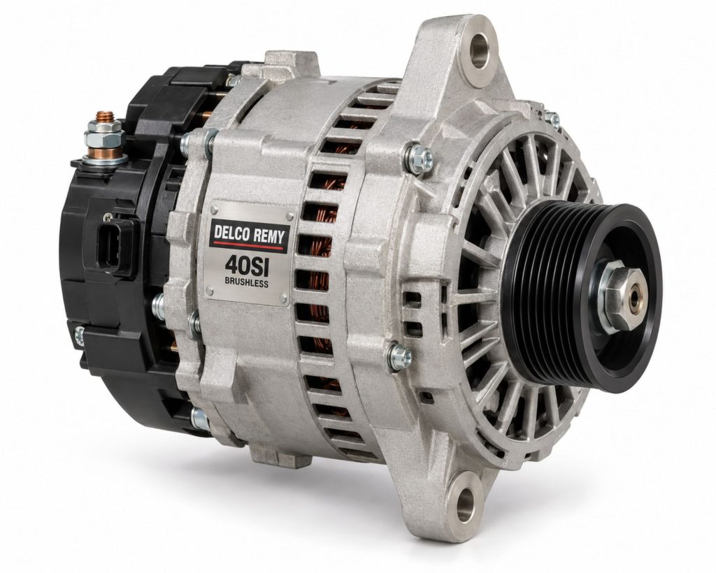
Overview
The Delco Remy 40SI is a high-output brushless alternator developed for heavy-duty commercial vehicles with demanding electrical loads. It converts mechanical energy supplied by the engine’s accessory drive into regulated electrical power for vehicle systems while maintaining battery charge.
The 40SI family includes 12-volt configurations rated from 240 through 320 amps. Delco Remy also lists application-specific 24-volt versions, including a 160-amp configuration. The exact output, mounting style, terminals, pulley, regulator, and connection arrangement depend on the complete part number.
Its brushless construction eliminates the brushes and slip rings used to carry field current in many conventional alternators. Removing those wear points can support longer service life in high-mileage, high-vibration, and high-duty-cycle commercial applications.
The 40SI is commonly selected for highway tractors, buses, emergency vehicles, refuse trucks, utility vehicles, vocational equipment, and other vehicles supporting substantial electrical demand.
Key Characteristics
- Heavy-duty brushless electrical design
- High-output 12-volt configurations from 240 through 320 amps
- Application-specific 24-volt configurations
- Strong output at engine idle
- Up to 72-percent published efficiency
- Remote Sense capability on applicable models
- J180 short-hinge mounting
- J180 long-hinge mounting
- Pad-mount configurations
- Designed for high-demand commercial electrical systems
- Service components available for supported configurations
- Multiple part numbers for different terminals, pulleys, and applications
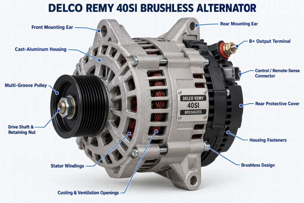
Major Components
- Drive-end housing
- Rectifier-end housing and protective cover
- Rotor assembly
- Stator assembly
- Rectifier assembly
- Voltage regulator
- Ball bearings
- Cooling fan
- Drive pulley
- B+ output terminal
- Ground connection
- Remote Sense terminal on applicable models
- R and I terminals where specified
- Mounting feet or pad-mount structure
- Internal conductors and insulated connections
Product Type and Construction
The 40SI is an engine-driven, internally regulated heavy-duty alternator. Its housings support the rotor, stator, bearings, rectifier, regulator, terminals, pulley, fan, and mounting structure as one assembly.
Brushless construction distinguishes the 40SI from alternators that use brushes and slip rings to carry electrical current into the rotating field. The absence of those wear components reduces one source of mechanical and electrical deterioration.
The alternator is available with multiple mounting arrangements so it can be matched to different engine brackets and accessory-drive layouts. Housing, terminal, regulator, and pulley differences mean that two 40SI alternators should not be considered interchangeable without checking their complete part numbers.
How the Electrical Component or System Works
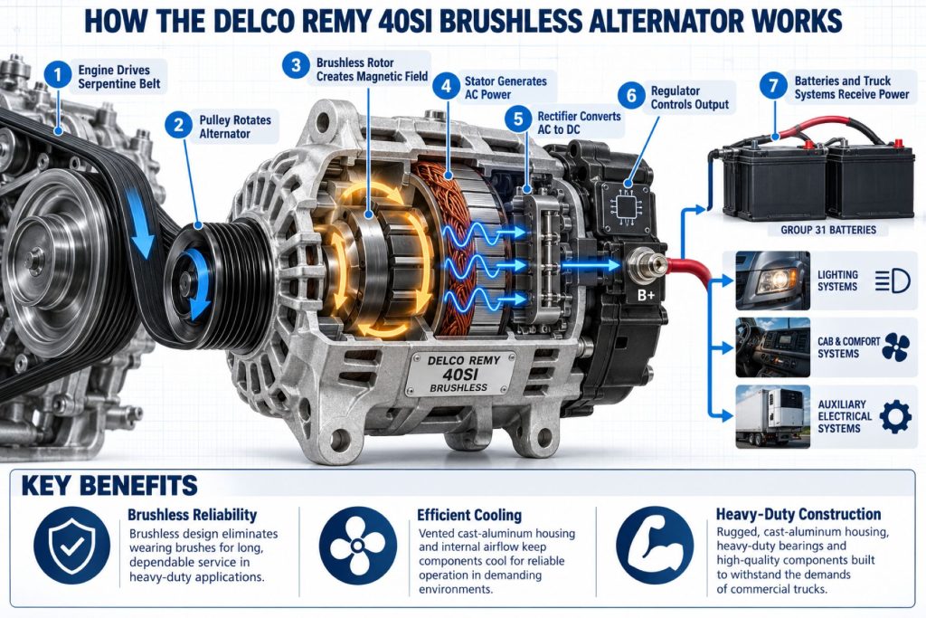
The engine rotates the alternator pulley through an accessory-drive belt. This turns the rotor inside the stationary stator and creates a changing magnetic field.
Electrical energy generated in the stator begins as alternating current. The rectifier converts this output into direct current that can supply the vehicle’s electrical system and recharge its batteries.
The internal regulator controls alternator operation to maintain the required system voltage. On configurations using Remote Sense, the regulator can monitor voltage at a point elsewhere in the vehicle’s electrical system and compensate for voltage loss between the alternator and batteries.
Position and Function Within the Vehicle
The 40SI is mounted on the engine and driven by the engine’s accessory belt system. Its exact position depends on the engine, chassis, mounting bracket, belt arrangement, cooling package, and other installed accessories.
The alternator supplies electrical energy for vehicle loads that can include engine controls, lighting, HVAC blowers, emissions equipment, safety electronics, communication systems, sleeper accessories, refrigeration controls, lift equipment, and battery charging.
When electrical demand exceeds alternator output at a particular engine speed, the batteries supply the difference. When alternator output exceeds current vehicle demand, available energy can restore battery charge.
Common Specifications
- Alternator Type: Internally regulated heavy-duty brushless alternator
- Common System Voltage: 12 volts
- Published 12-Volt Output Ratings: 240, 275, 300, and 320 amps
- Published Idle Output: Approximately 160 to 190 amps, depending on configuration
- Published 24-Volt Example: 160 amps on application-specific configurations
- Published Efficiency: Up to 72 percent
- Maximum Continuous Speed: 8,000 rpm on published configurations
- Maximum Intermittent Speed: 10,000 rpm on published configurations
- Rotation: Clockwise on published 12-volt models
- Mounting: J180 short hinge, J180 long hinge, or pad mount
- Published Weight: Approximately 31 pounds or 14.1 kilograms
- Remote Sense: Available on applicable part numbers
Specifications vary by part number. The vehicle application, electrical rating, mounting style, pulley, terminal dimensions, regulator, and connection arrangement must be verified before installation.
Operating Capacity and Performance
The 40SI family is designed to provide substantial electrical output at both road speed and engine idle. Published 12-volt ratings extend from 240 to 320 amps, while published idle output ranges from approximately 160 to 190 amps depending on the configuration.
Actual output depends on alternator speed, system voltage, ambient temperature, alternator temperature, battery condition, wiring resistance, belt condition, regulator strategy, and active electrical demand.
A 320-amp nameplate rating does not mean that the alternator produces 320 amps during every operating condition. Output curves and application information for the exact part number should be used when evaluating idle performance and continuous demand.
Installation Position and System Function
The alternator must be installed on an approved engine bracket with the correct mounting hardware, alignment, belt, tensioning system, pulley ratio, and electrical connections.
Its primary function is to support active vehicle loads and maintain the batteries while the engine operates. It is not intended to correct an undersized battery bank, damaged cables, poor grounds, excessive parasitic loads, or an electrical system that continuously demands more current than the complete charging system can supply.
System Voltage and Electrical Architecture
Most 40SI applications use a negative-ground 12-volt electrical system, although application-specific 24-volt configurations are available. The alternator voltage must match the vehicle’s electrical architecture.
Commercial trucks may use multiple 12-volt batteries connected in parallel to increase available capacity while maintaining a 12-volt system. Other vehicles may use series-connected batteries to support a 24-volt architecture.
The alternator, batteries, starter, cables, controls, electrical loads, and protective devices must all be compatible with the system voltage and grounding arrangement.
Electrical Input, Output, and Power Function
The 40SI receives mechanical input through its pulley and produces regulated DC electrical output through its B+ terminal and grounding path. Control and monitoring terminals vary according to the exact configuration.
Required mechanical input increases with electrical output. A more efficient alternator requires less engine power than a less efficient unit producing the same electrical output, which can reduce the fuel energy consumed to support vehicle electrical demand.
Output wiring, grounds, battery connections, and protective devices must safely support the alternator’s maximum available current.
Voltage, Current, and Electrical Load Management
The voltage regulator manages alternator output according to system conditions. Current demand changes as lighting, HVAC equipment, engine controls, safety systems, auxiliary equipment, and battery charging needs change.
High electrical demand at low engine speed is particularly important in emergency, refuse, utility, transit, delivery, and vocational service. The selected alternator must provide adequate output at the actual operating speed rather than only at its maximum rating.
Load studies should account for continuous loads, intermittent loads, battery recovery, seasonal HVAC demand, auxiliary equipment, idle time, and planned future accessories.
Charging and Battery-Support Function
The 40SI supports the vehicle’s electrical loads while providing available current to recharge the battery bank. Charging performance depends on battery state of charge, battery chemistry, temperature, cable resistance, regulator strategy, and alternator speed.
An alternator should not be used as the primary recovery method for a severely discharged or damaged battery bank unless the vehicle and component manufacturers approve the procedure. Deeply discharged batteries can place sustained high demand on the charging system.
Battery condition should be verified whenever an alternator is replaced. Weak or internally damaged batteries can contribute to poor charging performance and shorten the life of replacement components.
Circuit Design and Power Distribution
The alternator’s output circuit typically connects the B+ terminal to the battery and vehicle power-distribution system through heavy-gauge cabling and approved protective arrangements.
The circuit must minimize resistance while supporting the expected current. Excessive resistance at cables, terminals, battery connections, junction points, or grounds can reduce charging voltage and create damaging heat.
Vehicles using battery isolators, high-current relays, auxiliary battery banks, liftgate charging systems, inverters, or trailer-power systems require additional compatibility review.
Internal Components and Electrical Design
The rotating field and stationary stator generate electrical energy. The rectifier converts the stator’s alternating current into direct current, while the regulator manages field strength and system voltage.
The brushless design removes conventional brush and slip-ring wear points. Bearings still support the rotating assembly, and the fan moves cooling air through the alternator.
Internal electrical and mechanical parts remain subject to heat, vibration, contamination, overspeed, improper belt loading, connection problems, and abnormal system demand.
Materials and Component Construction
The alternator uses metal housings, copper windings, insulated conductors, semiconductor rectifier components, bearings, steel mounting hardware, an external fan, and application-specific terminal materials.
Housing openings support cooling airflow while the rear cover protects electrical components. Mounting structures must withstand belt force, engine vibration, thermal cycling, and the weight of the alternator.
Material, housing, terminal, and internal component details may differ between production revisions and part numbers.
Wiring, Terminals, Connectors, and Grounding
The B+ output cable and ground path must be sized for the alternator’s output, cable length, routing, temperature exposure, and vehicle electrical architecture.
Applicable 40SI configurations may include:
- B+ output terminal
- Negative-ground connection
- Remote Sense terminal
- R terminal
- I terminal
- Application-specific connector or harness arrangements
Terminal dimensions can vary by part number. Every cable and control lead should be connected to the correct terminal and tightened according to approved service information.
Circuit Protection and Electrical Safety
The charging circuit must use approved protection, routing, insulation, support, and terminal covers. Requirements depend on the vehicle manufacturer and electrical-system design.
Battery power should be isolated according to approved procedures before alternator wiring is disconnected. Accidental contact between an energized output terminal and ground can produce severe current, arcing, heat, component damage, or fire.
Protective devices should never be bypassed or replaced with equipment that exceeds the circuit’s approved rating.
Controls, Monitoring, and Diagnostics
Vehicle instruments or electronic controllers may monitor charging voltage, warning-lamp status, alternator signals, battery condition, or energy-management information.
The exact control arrangement depends on the alternator part number and vehicle. Some systems use conventional warning circuits, while others integrate the charging system with electronic controls and networked diagnostics.
Diagnostic work should include direct voltage measurements at the alternator and batteries rather than relying only on dashboard information.
Power Demand, Capacity, and Energy Management
Alternator selection should be based on a realistic electrical-load analysis. Continuous vehicle demand should remain within the charging system’s sustainable output under the engine speeds and temperatures encountered in service.
Common high-demand loads include:
- Cab and sleeper HVAC equipment
- Exterior and work lighting
- Electric cooling fans
- Heated glass and mirrors
- Refrigeration and auxiliary equipment
- Emergency warning systems
- Liftgates and hydraulic controls
- Inverters and sleeper accessories
- Telematics and communication equipment
- Battery recovery after engine-off operation
Power Consumption and System Efficiency
Delco Remy publishes an efficiency rating of up to 72 percent for the 40SI. Higher alternator efficiency reduces the mechanical power required from the engine to produce a given amount of electrical power.
Actual fuel and operating benefits depend on vehicle duty cycle, average electrical demand, engine operating time, alternator speed, battery condition, and the efficiency of the complete electrical system.
Poor cables, weak batteries, damaged connections, or excessive loads can reduce system efficiency even when the alternator itself is operating correctly.
Heat, Efficiency, and Electrical Loss Management
Alternator operation creates heat within the windings, rectifier, regulator, bearings, cables, and terminals. Cooling airflow and correct installation help keep component temperatures within their designed limits.
Resistance at a loose or corroded connection converts electrical energy into heat. Overheated terminals, hardened insulation, melted covers, discoloration, or a burning odor require immediate investigation.
Delco Remy publishes different temperature ratings for particular 40SI output levels. The exact rating should be confirmed for the selected part number.
Environmental Sealing and Contamination Protection
The alternator should be protected from direct pressure washing, oil saturation, fuel contamination, road chemicals, debris accumulation, and fluid leaks from nearby components.
Cooling openings must remain clear. Oil, dust, salt, and debris can reduce heat transfer, damage insulation, contaminate connections, and accelerate corrosion.
Environmental exposure should be considered when selecting the mounting location and exact alternator configuration for vocational or severe-service vehicles.
Duty Cycle and Operating Conditions
The 40SI is designed for demanding commercial service, but alternator loading varies considerably between highway, urban, vocational, emergency, bus, and specialty applications.
Vehicles that spend substantial time idling may require strong low-speed output. Vehicles with sleeper accessories or auxiliary batteries may require extended battery-recovery capability. Emergency and vocational vehicles may operate lighting, pumps, controls, communication equipment, and other loads simultaneously.
Temperature, engine speed, dust, moisture, vibration, belt loading, and maintenance practices all influence service life.
Mounting and Installation
Installation requires the correct alternator part number, mounting style, pulley, belt arrangement, hardware, electrical terminals, and vehicle compatibility.
The mounting bracket should be inspected for cracks, looseness, distortion, corrosion, and damaged threads. The pulley must align with the other accessory-drive components, and belt tension must follow the engine and tensioner requirements.
Cables should be routed away from exhaust heat, sharp edges, moving parts, and areas where vibration can cause abrasion. Terminal boots and protective covers should be restored after installation.
Wiring, Grounding, and Installation Requirements
Output and ground circuits should be evaluated for conductor size, total length, terminal condition, routing, voltage drop, and current capacity.
Grounding through the alternator housing and engine may be supplemented by dedicated ground cabling depending on the vehicle design. Engine-to-frame and battery-to-engine grounds must also remain in good condition.
Remote Sense wiring must be connected according to the approved diagram. Incorrect sensing connections can cause charging problems or inaccurate voltage regulation.
Vehicle and Electrical-System Compatibility
Compatibility depends on the vehicle, engine, system voltage, mounting bracket, pulley ratio, belt system, electrical demand, cable capacity, terminal arrangement, regulator strategy, and available clearance.
A compatible installation must confirm:
- Correct system voltage
- Required rated and idle output
- J180 or pad-mount configuration
- Mounting dimensions
- Pulley and belt compatibility
- Correct direction of rotation
- Terminal type and location
- Remote Sense requirements
- Output-cable and grounding capacity
- Vehicle-control compatibility
- Physical and cooling clearance
Battery and Charging-System Compatibility
The 40SI must be paired with batteries and charging controls appropriate for the vehicle’s nominal voltage and operating requirements.
Battery-bank size, chemistry, age, state of charge, cable condition, and auxiliary loads affect alternator operation. Vehicles using flooded, AGM, or other approved battery technologies may require different charging and energy-management considerations.
Battery isolators, DC-to-DC chargers, auxiliary battery banks, and inverter systems must be evaluated for their effect on alternator loading and voltage regulation.
Related Component and System Compatibility
The alternator interacts with the engine accessory drive, battery bank, starter, power-distribution system, vehicle controllers, lighting, HVAC equipment, safety systems, telematics, and auxiliary electrical loads.
Changing alternator output may require an engineering review of cables, terminals, circuit protection, belt drive, mounting brackets, batteries, controls, and power-distribution components.
Common Applications
- Long-haul sleeper tractors
- Regional and day-cab tractors
- Heavy-duty vocational trucks
- Refuse trucks
- Utility and service vehicles
- Emergency vehicles
- Transit buses
- School buses
- Motorcoaches
- Construction equipment
- Transport refrigeration and auxiliary-power applications
- Commercial vehicles with substantial idle-time electrical loads
Advantages
- High electrical output
- Strong output at engine idle
- Brushless construction removes brush and slip-ring wear
- Up to 72-percent published efficiency
- Multiple output ratings
- Three major mounting configurations
- Remote Sense capability on applicable models
- Suitable for high-demand commercial vehicles
- Replacement and service support through Delco Remy distribution
- Can support reduced engine-power demand compared with a less efficient alternator
Limitations or Considerations
- Higher-output installations require suitable cables and connections
- Not every 40SI part number is interchangeable
- Mounting style must match the engine bracket
- Pulley ratio and belt capacity must be verified
- Incorrect alignment can damage belts and bearings
- Excessive electrical demand can exceed idle output
- Weak batteries can place sustained demand on the alternator
- Cooling airflow must remain unobstructed
- Remote Sense wiring must be correctly connected
- Higher rated output does not correct poor wiring or grounding
Driver and Operator Experience
A correctly operating 40SI should maintain stable electrical performance without requiring routine driver adjustment. The operator may notice improved voltage stability when lighting, HVAC equipment, sleeper accessories, or other substantial loads are active.
Drivers should report charging warnings, dim or flickering lamps, slow cranking, repeated battery discharge, electrical odors, belt noise, unusual bearing noise, or changing instrument voltage.
Continued operation with an active charging-system warning can discharge the batteries and eventually cause the engine or essential electronic systems to stop operating.
Controls, Indicators, and Driver Feedback
Driver feedback may include a charging-system warning lamp, voltage gauge, dashboard message, audible warning, battery-management display, or remotely monitored fleet fault.
A normal dashboard voltage reading does not prove that every charging-system connection is in good condition. High resistance may exist between the alternator, batteries, power-distribution system, or cab instruments.
Warnings should be evaluated using vehicle-specific diagnostic information and direct electrical measurements.
Common Electrical Tests and Diagnostic Information
Charging-system diagnosis may include:
- Battery state-of-charge testing
- Battery load or conductance testing
- Charging voltage measurement
- Alternator current-output testing
- Output-circuit voltage-drop testing
- Ground-circuit voltage-drop testing
- Belt and tensioner inspection
- Pulley-speed verification
- Remote Sense circuit inspection
- Parasitic-load testing
- Vehicle fault-code review
- Connection-temperature inspection
Testing should be completed with equipment rated for the expected voltage and current. Manufacturer procedures should be followed for the exact vehicle and alternator.
Inspection and Wear Points
- Mounting brackets and fasteners
- Drive pulley
- Accessory-drive belt
- Belt tensioner and idlers
- Alternator bearings
- B+ terminal and output cable
- Grounding path
- Remote Sense and control terminals
- Connector locks and seals
- Rear protective cover
- Cooling openings and fan
- Signs of oil, coolant, fuel, or water contamination
- Heat discoloration or damaged insulation
Cooling, Ventilation, and Environmental Requirements
The alternator’s fan and housing openings move cooling air around internal components. These areas should remain free of packed debris, heavy oil deposits, and obstructions.
Engine-compartment temperature, airflow, nearby exhaust components, and sustained electrical output affect operating temperature. Installation should preserve the clearances and airflow intended by the vehicle manufacturer.
Direct pressure washing can force moisture and contaminants into electrical or bearing areas and should be avoided unless specifically permitted by service instructions.
Component Service Life and Rebuildability
The 40SI’s brushless construction removes two conventional wear components, but service life still depends on operating temperature, bearing load, belt alignment, vibration, electrical demand, contamination, and connection quality.
Delco Remy lists replacement-component instructions and service parts for supported 40SI configurations. Available components can include bearings, rotor assemblies, frames, covers, fans, and other application-specific parts.
Repair or rebuilding should be completed using approved components and procedures. In some situations, complete alternator replacement may be more practical than field repair.
Maintenance and Ownership Notes
Inspect the alternator, belt system, wiring, terminals, batteries, and grounds at scheduled service intervals. Keep connections clean, tight, protected, and correctly supported.
Charging-system problems should be corrected before they damage batteries or other electrical components. Repeated alternator failure warrants a complete review of electrical demand, cable voltage drop, grounds, battery condition, belt drive, heat, vibration, and contamination.
Replacement records should include the vehicle VIN, engine, alternator part number, output rating, mounting style, pulley information, terminal configuration, and installation date.
Common Electrical-System Problems
- Low charging voltage: A slipping belt, low alternator output, excessive resistance, poor grounding, damaged Remote Sense circuit, weak batteries, or excessive load may be responsible.
- No alternator output: An open circuit, failed regulator, internal damage, broken belt, incorrect wiring, or control-circuit fault may prevent charging.
- Overcharging: Incorrect sensing, poor battery connections, regulator failure, improper wiring, or an incompatible alternator can produce excessive voltage.
- Overheated output terminal: A loose connection, corrosion, damaged cable, insufficient conductor size, or excessive current can create heat.
- Belt noise: Misalignment, incorrect tension, a worn pulley, damaged tensioner, contamination, or alternator-bearing resistance may cause noise.
- Bearing noise: Wear, contamination, excessive belt load, misalignment, or internal damage may create grinding, growling, or whining sounds.
- Repeated battery discharge: Insufficient alternator output, excessive parked loads, weak batteries, poor connections, short duty cycles, or an undersized charging system may be responsible.
- Intermittent charging: Loose terminals, damaged wiring, vibration, regulator problems, belt slip, or heat-related internal faults may cause changing output.
Safety and Service Precautions
Disconnect and isolate battery power according to approved procedures before removing alternator wiring or beginning service. High-current battery circuits can cause severe arcing, burns, component damage, or fire.
Never disconnect a battery cable while the engine is running as an alternator test. That practice can create voltage spikes and damage electronic equipment.
Keep tools, jewelry, and conductive objects away from energized terminals. Support the alternator during removal because its published weight is approximately 31 pounds. Follow approved lifting, belt-release, torque, wiring, and testing procedures.
Identification Information
Identification information is normally located on the alternator label, housing, parts records, or vehicle build information.
Record the following before ordering replacement equipment:
- Complete Delco Remy part number
- 40SI model designation
- System voltage
- Rated output
- Mounting style
- Pulley type and dimensions
- Terminal sizes and locations
- Remote Sense configuration
- Ground polarity
- Vehicle VIN
- Engine manufacturer and model
- Original-equipment specification
Do not identify an alternator only by appearance or its 40SI family name. Part-number differences can affect mounting, output, terminals, regulator operation, pulley compatibility, and vehicle integration.
Buying Considerations
- Verify the complete Delco Remy part number
- Confirm 12-volt or 24-volt operation
- Select the required rated and idle output
- Match the J180 or pad-mount arrangement
- Confirm pulley and belt compatibility
- Match every terminal and connector
- Verify Remote Sense requirements
- Check output-cable and grounding capacity
- Review the vehicle’s actual electrical demand
- Determine whether programming or configuration is required
- Compare new, remanufactured, and approved replacement options
- Confirm warranty and core requirements
- Use a qualified heavy-duty electrical supplier or installer
Variants and Configurations
- 12-volt 240-amp configurations
- 12-volt 275-amp configurations
- 12-volt 300-amp configurations
- 12-volt 320-amp configurations
- Application-specific 24-volt configurations
- J180 short-hinge mount
- J180 long-hinge mount
- Pad mount
- Different pulleys and belt arrangements
- Different terminal dimensions
- Remote Sense configurations
- Original-equipment and replacement applications
Comparison to Similar Equipment
Compared with the Delco Remy 36SI High-Output Alternator, the 40SI provides a different output range, physical package, and application coverage. The correct selection depends on the vehicle’s required output, mounting arrangement, pulley, terminals, and available space.
Compared with the Delco Remy 28SI High-Output Alternator, the 40SI is intended for applications requiring greater electrical output and a heavy-duty brushless design.
Compared with the Leece-Neville IdlePro Alternator, the 40SI offers a Delco Remy alternative with its own output ratings, mounting configurations, terminal arrangements, regulator features, and replacement coverage.
Compared with a conventional brushed alternator, the 40SI eliminates brushes and slip rings from its field-current design. A brushed alternator may be suitable for lower-demand applications but contains additional wear components.
Best Fit For
- Heavy-duty vehicles with high electrical demand
- Trucks requiring strong alternator output at idle
- Long-haul tractors with sleeper electrical loads
- Emergency vehicles with extensive lighting and communications
- Transit and school buses
- Refuse and vocational trucks
- Vehicles using auxiliary battery systems
- Fleets seeking a brushless heavy-duty alternator
- Applications requiring J180 or pad mounting
- Vehicles originally specified for a compatible 40SI configuration
Related Vehicle and Trailer Types
- Long-Haul Sleeper Trucks
- Day Cab Trucks
- Heavy-Haul Trucks
- Dump Trucks
- Refuse trucks
- Utility trucks
- Emergency vehicles
- Transit buses
- School buses
- Specialized commercial vehicles
Related Truck and Trailer Models
- Freightliner Cascadia
- Kenworth T680
- Kenworth T880
- Peterbilt 579
- Peterbilt 567
- Volvo VNL
- International LT Series
- Mack Anthem
- Mack Granite
- Western Star 57X
Related Electrical System Types
- Alternators & Charging Systems
- Commercial Truck Batteries & Energy Storage
- Starters & Starting Systems
- Wiring, Connectors & Power Distribution
- Inverters, Converters & Auxiliary Electrical Power
- Brushless alternators
- Brushed alternators
- High-output alternators
- Dual-alternator systems
Related Electrical Products
- Delco Remy 36SI High-Output Alternator
- Delco Remy 28SI High-Output Alternator
- Delco Remy 24SI Heavy-Duty Alternator
- Delco Remy 39MT Heavy-Duty Gear-Reduction Starter
- Delco Remy 38MT Heavy-Duty Starter
- Leece-Neville IdlePro Alternator
- Leece-Neville IdlePro Extreme Alternator
- Deka Intimidator AGM Group 31 Battery
Related Equipment Systems
- Electrical Systems
- Engines
- Transmissions
- Truck & Trailer Lighting Systems
- Telematics & ELD Systems
- Safety Systems
- Equipment Systems
Related Guides
- Electrical System Guides
- How Commercial Truck Electrical Systems Work
- Commercial Truck Batteries Explained
- Commercial Truck Alternators and Charging Systems Explained
- Commercial Truck Starters and Starting Systems Explained
- How to Inspect and Maintain Truck Wiring and Electrical Connections
- Commercial Truck and Trailer Lighting Systems Explained
Regulatory and Compliance Notes
Charging-system changes must preserve compliance with vehicle electrical, emissions, lighting, braking, safety, and electronic-control requirements.
Replacement wiring, circuit protection, terminals, and mounting components must meet the requirements of the vehicle and component manufacturers. Modifications should not interfere with required lighting, safety systems, emissions controls, engine operation, or diagnostic functions.
Emergency vehicles, buses, refrigerated equipment, and other specialized vehicles may be subject to additional electrical-capacity, redundancy, inspection, or operational requirements.
Real World Operating Notes
High-output alternators are most effective when the complete charging system is properly sized. Installing a 40SI without correcting undersized cables, poor grounds, weak batteries, or an overloaded accessory drive may not resolve the original problem.
Idle output matters on vehicles that spend substantial time parked with the engine running. Emergency vehicles, refuse trucks, buses, and utility vehicles can operate large electrical loads at low engine speed.
Repeated battery replacement may indicate inadequate charging time, parasitic demand, excessive engine-off loads, poor connections, or insufficient alternator output rather than defective batteries alone.
Charging-system voltage should be measured under realistic operating conditions with normal vehicle loads active.
Frequently Asked Questions
What is the Delco Remy 40SI?
The 40SI is a heavy-duty brushless alternator family designed to supply high electrical output for commercial trucks, buses, emergency vehicles, vocational equipment, and other demanding applications.
How much output does the 40SI provide?
Published 12-volt configurations are available with ratings of 240, 275, 300, or 320 amps. Application-specific 24-volt configurations are also available.
Is the 40SI brushless?
Yes. Its brushless design eliminates conventional brushes and slip rings used to carry field current.
What mounting styles are available?
Delco Remy lists J180 short-hinge, J180 long-hinge, and pad-mount configurations within the 40SI family.
What is Remote Sense?
Remote Sense allows the regulator to monitor voltage at a selected point in the vehicle’s electrical system and compensate for voltage loss between the alternator and that location.
Can a higher-output 40SI replace a lower-output alternator?
Only after confirming mounting, pulley, belt, terminal, wiring, circuit-protection, regulator, control, and vehicle compatibility. Output rating alone does not establish interchangeability.
Why does alternator output decrease at idle?
Alternator output depends partly on rotor speed. At low engine speed, the alternator turns more slowly and may produce less current than its maximum road-speed rating.
Can the 40SI charge AGM batteries?
Compatibility depends on the complete vehicle charging strategy and the requirements of the installed batteries. Battery manufacturer and vehicle information should be verified.
What commonly causes a 40SI installation to overheat?
Possible causes include sustained excessive load, poor cooling airflow, high resistance, loose terminals, undersized cables, weak batteries, contamination, or an incorrect installation.
How can the correct replacement be identified?
Use the complete Delco Remy part number, vehicle VIN, system voltage, output rating, mounting style, pulley, terminals, Remote Sense configuration, engine information, and original-equipment records.
Availability and Where to Find
Delco Remy 40SI alternators and supported service components may be available through heavy-duty truck dealers, electrical specialists, fleet-parts suppliers, commercial-vehicle distributors, engine dealers, and authorized Delco Remy channels.
Availability depends on system voltage, output rating, mounting style, terminal arrangement, pulley, regulator configuration, and application. Buyers should confirm whether the unit is new, remanufactured, original-equipment, approved replacement, or an all-makes configuration.
Current product details, part-number lookup, installation instructions, technical support, and distributor information are available through the Delco Remy 40SI product page.
Support Trucking Families
Truck Equipment Atlas supports the mission of Grey Cross, a nonprofit dedicated to helping families of truck drivers who lose their lives while on the road. As the site grows, part of its mission is to bring awareness and support to these families.
Podcast or Video Section
Learn More Through Audio and Video
Truck Equipment Atlas will continue expanding with podcast episodes, interviews, and equipment breakdowns to help drivers and fleets better understand trucks and equipment.
Follow the Growth of Truck Equipment Atlas
Truck Equipment Atlas continues to expand with new truck profiles, trailer coverage, diesel engine pages, equipment-system resources, manufacturer information, and educational guides.
Visit our Site Updates page to explore recent additions, project milestones, and upcoming resources as we continue building one of the industry’s growing commercial trucking equipment reference libraries.
View the Latest Site Updates: Truck Equipment Atlas Site Updates