
Quick Facts
- Manufacturer: Delco Remy
- Product Family: 39MT
- Product Type: Heavy-duty gear-reduction starter
- Motor Design: Wound-field motor with planetary reduction gears
- System Voltage: 12 or 24 volts
- Engine Compatibility: 12-volt applications up to 15 liters; 24-volt applications up to 16 liters
- Peak Output: 7.3 kilowatts at 12 volts or 9.0 kilowatts at 24 volts
- Rotation: Clockwise
- Mounting: SAE No. 1 or SAE No. 3 for applicable 12-volt models; SAE No. 3 for 24-volt models
- Drive Design: Electrical soft-start with overrunning clutch
- Pinion Support: Noseless
- Primary Applications: Heavy-duty trucks, vocational vehicles, buses, construction equipment, agricultural machinery, and off-highway equipment
- Production Status: Available in application-specific new and replacement configurations
Overview
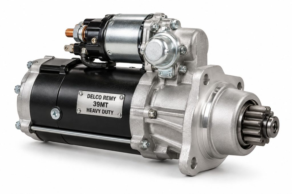
The Delco Remy 39MT is a heavy-duty gear-reduction starter designed for large commercial diesel engines and demanding off-highway applications. It combines a high-output electric motor with planetary reduction gears that multiply cranking torque while controlling starter size and weight.
The 39MT uses an electrical soft-start system that begins rotating the pinion before full cranking torque is applied. This helps the pinion engage the engine’s ring gear properly and reduces tooth-abutment damage.
Available features vary by part number and may include Over-Crank Protection, Jump-Start Protection, an Integral Magnetic Switch, and a rotatable mounting flange. The complete part number must be used when confirming voltage, mounting, pinion, protection features, and engine compatibility.
Key Characteristics
- Heavy-duty planetary gear-reduction starter
- Available for 12-volt and 24-volt systems
- Supports large commercial diesel engines
- Electrical soft-start pinion engagement
- Noseless sealed configuration
- Overrunning clutch
- Sealed solid-link solenoid design
- Clockwise rotation
- Multiple pinion configurations
- Optional rotatable mounting flange
- Optional Over-Crank Protection
- Optional Jump-Start Protection
- Integral Magnetic Switch on applicable models
- Designed for truck and off-highway service
Major Components
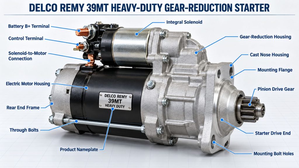
- Wound-field electric motor
- Armature
- Field coils
- Brushes and brush holder
- Commutator
- Planetary reduction-gear assembly
- Drive shaft
- Pinion gear
- Overrunning clutch
- Shift lever
- Electrical soft-start drive
- Starter solenoid
- Integral Magnetic Switch where equipped
- Drive-end housing
- Commutator-end housing
- Mounting flange
- Over-Crank Protection device where equipped
- Jump-Start Protection device where equipped
- Electrical terminals and internal conductors
Product Type and Construction
The 39MT is a wound-field starter motor with a planetary gear-reduction system. The electric motor turns faster than the starter pinion, while the reduction gears convert that speed into the high torque required to crank a large diesel engine.
Its noseless drive-end configuration limits openings where dirt and debris can collect. A sealed solenoid and application-specific protection features help the starter operate under demanding commercial-vehicle conditions.
How the Electrical Component or System Works
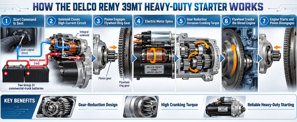
When the operator activates the starting circuit, low-current control power energizes the starter’s switching and solenoid circuits. The solenoid moves the pinion toward the engine flywheel or flexplate ring gear.
The electrical soft-start system initially rotates the pinion at reduced force so its teeth can align with the ring gear. After engagement, the main contacts close and battery current flows to the starter motor.
The electric motor drives the planetary reduction gears, which multiply torque before sending it through the overrunning clutch and pinion. Once the engine starts, the clutch prevents the running engine from overspeeding the starter motor, and the pinion retracts when the start command ends.
Position and Function Within the Vehicle
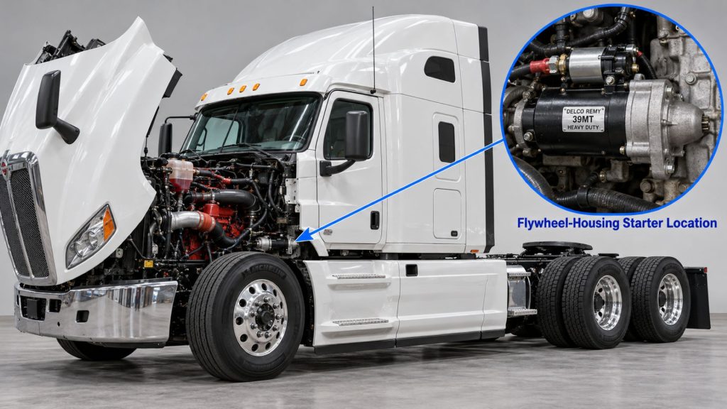
The 39MT mounts to the engine’s flywheel housing, where its pinion can engage the ring gear. Its primary function is to rotate the engine fast enough for compression, fuel delivery, and combustion to begin.
The starter receives high-current power from the vehicle’s battery bank and a control signal from the ignition switch, starter relay, engine controller, or starting-control system.
Common Specifications
- Starter Type: Heavy-duty gear-reduction starter
- Motor Type: Wound field
- Gear System: Planetary reduction gears
- System Voltage: 12 or 24 volts
- Maximum Engine Size at 12 Volts: Up to 15 liters
- Maximum Engine Size at 24 Volts: Up to 16 liters
- Peak 12-Volt Output: 7.3 kilowatts
- Peak 24-Volt Output: 9.0 kilowatts
- Rotation: Clockwise
- 12-Volt Mounting: SAE No. 1 or SAE No. 3, depending on model
- 24-Volt Mounting: SAE No. 3
- Pinion Options: 11-tooth 6/8 pitch, 12-tooth 8/10 pitch, or 12-tooth MOD 3 metric
- Pinion Support: Noseless
- Drive Design: Electrical soft-start with overrunning clutch
- Approximate Weight: 30.8 pounds or 14 kilograms
- Frame Diameter: Approximately 4.5 inches or 114 millimeters
- Overall Length: Approximately 14.09 inches or 358 millimeters
Exact polarity, solenoid position, pinion, mounting flange, protection features, terminals, and engine compatibility depend on the individual 39MT part number.
Operating Capacity and Performance
The 12-volt 39MT is designed for compatible engines up to 15 liters and has a published peak output of 7.3 kilowatts. The 24-volt version supports compatible engines up to 16 liters and has a published peak output of 9.0 kilowatts.
Actual cranking performance depends on battery state of charge, battery temperature, cable resistance, engine temperature, oil viscosity, starter condition, engine mechanical condition, and the compatibility of the pinion and ring gear.
Installation Position and System Function
The starter mounts directly to the engine flywheel housing. Its flange position, pinion reach, pinion tooth count, pitch, rotation, and solenoid position must match the engine installation.
Correct alignment allows the pinion to move into the ring gear, transfer cranking torque, and retract without binding or damaging either gear.
System Voltage and Electrical Architecture
The 39MT is offered for 12-volt and 24-volt starting systems. The selected starter must match the battery-bank voltage, charging system, engine controls, starting circuit, and vehicle wiring.
A 12-volt starter cannot be substituted for a 24-volt unit or the reverse. Individual part numbers may also use insulated or application-specific grounding arrangements.
Electrical Input, Output, and Power Function
The starter draws high current from the battery bank and converts electrical energy into mechanical torque. The planetary reduction gears increase the torque delivered to the pinion and engine ring gear.
Because starter operation creates a large but brief electrical load, battery capacity and low-resistance cable connections are essential for normal cranking speed.
Voltage, Current, and Electrical Load Management
Available voltage at the starter falls when battery condition is poor or resistance exists in the cables, switches, terminals, grounds, or solenoid circuit. Excessive voltage drop reduces motor speed and increases cranking time.
An Integral Magnetic Switch on applicable models helps reduce voltage loss in the solenoid control circuit and ensures the solenoid receives the strongest available activation voltage.
Starting and Cranking Function
The 39MT rotates the engine crankshaft through the flywheel or flexplate ring gear. The engine must reach adequate cranking speed for its electronic controls, fuel system, compression, and combustion process to begin operating.
Cold temperatures, heavy oil, weak batteries, damaged cables, and engine mechanical resistance can increase the torque and time required to start.
Circuit Design and Power Distribution
The starting circuit normally includes the battery bank, battery cables, grounds, disconnect switches, starter relay, Integral Magnetic Switch where equipped, solenoid, starter motor, ignition control, and engine-control interlocks.
High-current cables must be appropriately sized and routed. Loose, corroded, undersized, or damaged connections can prevent proper starter operation even when the batteries test correctly.
Internal Components and Electrical Design
The wound-field motor contains an armature, field coils, brushes, and commutator. When current flows through the field and armature circuits, electromagnetic force turns the motor shaft.
The solenoid moves the drive assembly and closes the high-current contacts. The planetary gears transmit motor output to the drive shaft at reduced speed and increased torque.
Materials and Component Construction
The 39MT uses steel shafts and gears, copper conductors and windings, carbon-based brushes, cast housings, bearings or bushings, electrical contacts, insulating materials, seals, and hardened pinion components.
Component life can be affected by heat, excessive cranking, vibration, corrosion, moisture, dirt, oil contamination, loose mounting, and incorrect ring-gear engagement.
Wiring, Terminals, Connectors, and Grounding
The battery terminal, motor connections, solenoid-control terminal, ground path, and Integral Magnetic Switch wiring must match the selected 39MT model and vehicle wiring diagram.
Terminals must be clean, properly tightened, and protected from accidental grounding. Grounded and insulated electrical configurations must not be interchanged without confirming the complete starting-system design.
Circuit Protection and Electrical Safety
Applicable 39MT models may include Over-Crank Protection. This automatically interrupts the starter circuit when excessive temperature develops and resets after the starter returns to a safe operating temperature.
Optional Jump-Start Protection is available for specified applications and is designed to meet SAE J1493 requirements. Protection features vary by part number and should never be assumed from external appearance.
Controls, Monitoring, and Diagnostics
The starter may receive its command through a mechanical ignition switch, starter relay, body controller, engine controller, neutral-safety circuit, clutch switch, or automated-transmission interlock.
Diagnosis should include battery state of charge, battery capacity, voltage drop, control-circuit voltage, starter current draw, cranking speed, mounting condition, pinion engagement, and engine mechanical resistance.
Electronic Controls and Driver-Assistance Integration
The 39MT may operate within an electronically controlled starting system that verifies transmission position, clutch position, engine status, battery voltage, and security authorization before permitting cranking.
The starter does not directly operate driver-assistance systems, but starting-system voltage problems can affect the electronic controllers required for normal vehicle operation.
Power Demand, Capacity, and Energy Management
Starter demand is highest during cold starts, low-battery conditions, and situations involving thick engine oil or elevated mechanical resistance. The battery bank must provide enough current while maintaining suitable voltage at the starter.
Repeated unsuccessful starts should not be treated as normal starter operation. The cause of poor starting should be diagnosed before continued cranking overheats the starter, cables, batteries, or connections.
Power Consumption and System Efficiency
The planetary gear-reduction design allows a relatively compact motor to develop the torque required for large diesel engines. The gears reduce pinion speed while multiplying torque at the ring gear.
Electrical losses increase when batteries, cables, switches, solenoid contacts, brushes, or internal conductors develop excessive resistance.
Heat, Efficiency, and Electrical Loss Management
Starter motors generate substantial heat because they operate at high current. Normal starts are brief, allowing the starter to cool between operating cycles.
Long cranking periods, repeated start attempts, low battery voltage, high cable resistance, a mechanically resistant engine, or a starter fault can increase heat. Over-Crank Protection helps protect equipped models from thermal damage.
Environmental Sealing and Contamination Protection
The noseless design reduces spaces where debris can accumulate near the drive assembly. The sealed solid-link solenoid is intended to improve reliability in demanding environments.
The starter should still be protected from direct pressure washing, road chemicals, deep water, oil leaks, loose debris, and damaged wiring. Sealed construction does not eliminate the need for inspection.
Duty Cycle and Operating Conditions
The 39MT is designed for short-duration cranking rather than continuous operation. Operators should follow the engine and vehicle manufacturers’ limits for maximum cranking time and required cooling intervals.
Cold climates, frequent stop-start service, construction sites, contamination, high vibration, and poorly maintained batteries can increase starter-system stress.
Mounting and Installation
Installation requires the correct SAE mounting flange, pinion tooth count, pinion pitch, pinion position, rotation, voltage, polarity, solenoid position, electrical terminals, and housing clearance.
Applicable rotatable-flange models can be repositioned according to Delco Remy instructions to align the starter with the engine. This feature does not make every 39MT compatible with every engine.
Wiring, Grounding, and Installation Requirements
- Disconnect battery power before removing the starter
- Verify 12-volt or 24-volt system compatibility
- Match the required SAE mounting flange
- Confirm pinion tooth count and pitch
- Confirm clockwise rotation
- Match the required solenoid position
- Use correctly sized battery cables
- Clean and secure all high-current connections
- Verify a low-resistance ground path
- Retain the Integral Magnetic Switch when specified
- Route wiring away from exhaust heat and moving components
- Tighten mounting hardware to the correct specification
- Test cranking voltage and voltage drop after installation
Vehicle and Electrical-System Compatibility
Compatibility depends on system voltage, engine model, flywheel housing, mounting flange, ring-gear design, pinion specifications, polarity, solenoid position, available clearance, and starting-control architecture.
The vehicle VIN, engine serial number, and original starter part number should be used when identifying a replacement. Similar-looking 39MT models may not be interchangeable.
Battery and Charging-System Compatibility
The battery bank must match the starter’s nominal voltage and provide sufficient cold-cranking capacity for the engine and operating environment. Battery connections, disconnect switches, grounds, and cables must support the starter’s high current demand.
The charging system must restore the energy removed during starting. An underperforming alternator can leave the batteries unable to support reliable cranking even when the starter is mechanically sound.
Related Component and System Compatibility
The 39MT must be matched with the engine ring gear, flywheel housing, batteries, charging system, battery cables, starter relay, control switches, engine electronics, and transmission safety interlocks.
An incompatible pinion or mounting arrangement can damage the starter drive and engine ring gear even if the electrical system operates normally.
Common Applications
- Heavy-duty highway tractors
- Regional-haul trucks
- Vocational trucks
- Dump trucks
- Concrete mixers
- Refuse trucks
- Heavy-haul tractors
- Construction equipment
- Mining equipment
- Agricultural machinery
- Transit buses
- Motor coaches
- Emergency vehicles
- Industrial diesel equipment
- Off-highway machinery
Advantages
- High cranking output for large diesel engines
- Available for 12-volt and 24-volt systems
- Planetary reduction gears multiply cranking torque
- Electrical soft-start improves pinion engagement
- Noseless design reduces debris accumulation
- Sealed solenoid supports demanding environments
- Overrunning clutch protects the starter after engine start
- Optional Over-Crank Protection
- Optional Jump-Start Protection
- Rotatable-flange options improve service flexibility
- Integral Magnetic Switch on applicable models
- Multiple pinion and mounting configurations
- Service components are available for applicable models
Limitations or Considerations
- Not designed for continuous operation
- Exact part numbers are not universally interchangeable
- Voltage must match the vehicle electrical system
- Pinion specifications must match the engine ring gear
- Mounting flange and solenoid position are application-specific
- Low battery voltage can cause poor engagement and overheating
- High-resistance cables can reduce cranking performance
- Protection features vary by part number
- Incorrect installation can damage the starter or ring gear
- Repeated long cranking cycles can create thermal damage
- Starter replacement will not correct engine or fuel-system problems
Driver and Operator Experience
A properly operating 39MT should engage quickly and crank the engine at a consistent speed. The electrical soft-start process occurs automatically and does not require a separate driver action.
Slow cranking, clicking, grinding, intermittent operation, delayed engagement, or failure to crank should be reported rather than addressed through repeated start attempts.
Controls, Indicators, and Driver Feedback
- Ignition or start switch
- Push-button starting control
- Neutral or clutch safety interlock
- Low-battery warning
- Engine-control warning message
- No-crank condition
- Slow-cranking sound
- Solenoid clicking
- Grinding during engagement
- Over-Crank Protection interruption where equipped
Common Electrical Tests and Diagnostic Information
- Battery state-of-charge test
- Battery load or conductance test
- Cranking-voltage measurement
- Starter current-draw test
- Positive-cable voltage-drop test
- Ground-side voltage-drop test
- Solenoid-control voltage test
- Starter-relay test
- Integral Magnetic Switch test
- Neutral-safety or clutch-switch test
- Engine cranking-speed measurement
- Diagnostic-code review
- Pinion and ring-gear inspection
Inspection and Wear Points
- Battery terminals
- Positive battery cables
- Ground cables and straps
- Starter terminals
- Solenoid connections
- Integral Magnetic Switch and wiring
- Mounting flange and bolts
- Starter housing
- Pinion teeth
- Ring-gear teeth
- Overrunning clutch
- Brushes and commutator
- Planetary gears
- Bushings and bearings
- Evidence of overheating or contamination
Cooling, Ventilation, and Environmental Requirements
The starter cools primarily during the periods between cranking cycles. It should be allowed to cool according to vehicle and engine instructions after an unsuccessful starting attempt.
Oil leaks, road debris, loose heat shields, exhaust heat, and direct pressure washing can affect starter life. Protective equipment should remain installed without trapping excessive heat around the starter.
Component Service Life and Rebuildability
Service life depends on starting frequency, cranking duration, battery condition, cable resistance, engine condition, temperature, vibration, and contamination.
Service kits may be available for brushes, field components, solenoids, pinions, drive shafts, levers, housings, protection devices, and Integral Magnetic Switches. Repair decisions should consider labor, component availability, starter condition, and fleet policy.
Maintenance and Ownership Notes
- Maintain batteries in a fully charged condition
- Inspect battery and ground cables
- Keep starter terminals clean and secure
- Check mounting bolts and flange condition
- Inspect wiring for heat and abrasion damage
- Investigate slow or intermittent cranking promptly
- Avoid extended cranking cycles
- Allow cooling time between unsuccessful starts
- Correct engine oil, fuel, and coolant leaks
- Inspect the pinion and ring gear after grinding complaints
- Do not remove the Integral Magnetic Switch when required
- Use the complete part number when ordering service parts
Common Electrical-System Problems
- No-crank condition: Discharged batteries, an open control circuit, defective relay, failed Integral Magnetic Switch, solenoid failure, damaged cables, or an internal starter fault may prevent operation.
- Single click without cranking: Low battery capacity, excessive cable resistance, solenoid-contact problems, a locked engine, or an internal starter fault may be responsible.
- Slow cranking: Weak batteries, cold temperatures, heavy oil, voltage drop, excessive engine resistance, worn brushes, or motor damage can reduce cranking speed.
- Grinding during engagement: Incorrect pinion specification, damaged pinion teeth, worn ring-gear teeth, loose mounting, or improper starter alignment may cause grinding.
- Pinion fails to engage: Low control voltage, solenoid failure, damaged shift components, contamination, or incorrect mounting geometry may prevent engagement.
- Starter remains engaged: A sticking solenoid, damaged control circuit, faulty ignition switch, welded relay contacts, or a binding drive may keep the starter operating.
- Repeated protection trips: Excessive cranking time, weak batteries, high resistance, difficult engine starting, or starter damage may activate Over-Crank Protection.
- Starter overheating: Long cranking cycles, repeated attempts, low voltage, excessive current draw, or an engine mechanical problem can generate excessive heat.
Safety and Service Precautions
Battery power must be disconnected according to the vehicle manufacturer’s procedure before the starter is removed or its wiring is serviced. Starter circuits can deliver enough current to cause severe arcing, burns, component damage, or fire.
The vehicle must be secured against movement, and the transmission must be placed in the required safe position. A heavy starter should be supported during removal and installation.
Never bypass safety interlocks or bridge starter terminals as a routine diagnostic method. Follow Delco Remy and vehicle-manufacturer procedures for testing, mounting, flange adjustment, wiring, and torque specifications.
Identification Information
Record the information on the starter identification label before ordering a replacement:
- Delco Remy model family
- Complete part number
- New or remanufactured status
- System voltage
- SAE mounting configuration
- Pinion tooth count
- Pinion pitch
- Solenoid position
- Clockwise rotation
- Grounded or insulated polarity
- Over-Crank Protection status
- Jump-Start Protection status
- Integral Magnetic Switch configuration
- Engine manufacturer and model
- Engine serial number
- Vehicle identification number
Buying Considerations
- Confirm 12-volt or 24-volt operation
- Verify engine model and displacement
- Match the original starter part number
- Confirm SAE No. 1 or SAE No. 3 mounting
- Match pinion tooth count and pitch
- Verify clockwise rotation
- Match the required solenoid position
- Confirm grounded or insulated configuration
- Determine whether Over-Crank Protection is required
- Determine whether Jump-Start Protection is required
- Verify Integral Magnetic Switch requirements
- Check rotatable-flange compatibility
- Inspect batteries, cables, and ring gear before replacement
- Compare new and remanufactured options
- Use the vehicle VIN and engine serial number
Variants and Configurations
- 12-volt starter configurations
- 24-volt starter configurations
- SAE No. 1 mounting on applicable 12-volt models
- SAE No. 3 mounting
- 11-tooth 6/8-pitch pinions
- 12-tooth 8/10-pitch pinions
- 12-tooth MOD 3 metric pinions
- Different solenoid positions
- Grounded or insulated configurations
- Fixed or rotatable mounting flanges
- Over-Crank Protection configurations
- Jump-Start Protection configurations
- Integral Magnetic Switch configurations
- New starter assemblies
- Remanufactured starter assemblies where available
Comparison to Similar Equipment
Compared with the Delco Remy 38MT Heavy-Duty Starter, the 39MT provides a newer heavy-duty gear-reduction platform with electrical soft-start engagement and additional application-specific protection options.
Compared with a direct-drive starter, the 39MT uses planetary reduction gears to multiply motor torque. This allows it to crank large diesel engines without relying on a larger direct-drive motor.
Compared with the Prestolite PowerPro Starter, the 39MT uses Delco Remy’s application-specific drive, mounting, solenoid, and protection designs. Selection should be based on verified engine and electrical compatibility.
Compared with the Prestolite PowerPro Extreme Starter, the 39MT offers a different combination of mounting, pinion, protection, and replacement configurations for heavy-duty applications.
Best Fit For
- Vehicles originally equipped with a compatible 39MT
- Heavy-duty diesel engines up to the approved displacement
- 12-volt commercial starting systems
- 24-volt commercial and off-highway systems
- Highway tractors
- Vocational trucks
- Construction and mining equipment
- Agricultural machinery
- Applications requiring electrical soft-start engagement
- Fleets requiring Over-Crank Protection options
- Applications using compatible rotatable-flange models
Related Vehicle and Trailer Types
- Complete Guide to Semi Truck Types
- Class 6 vs Class 7 vs Class 8 Trucks
- Heavy Haul Freight Guide
- Highway tractors
- Vocational trucks
- Dump trucks
- Concrete mixers
- Refuse trucks
- Construction equipment
- Transit buses
- Off-highway machinery
Related Truck and Trailer Models
- Freightliner Cascadia
- Freightliner 114SD
- Freightliner 122SD
- Kenworth T680
- Kenworth T880
- Peterbilt 579
- Peterbilt 567
- International LT Series
- Mack Anthem
- Volvo VNL
- Western Star 49X
Related Electrical System Types
- Starters & Starting Systems
- Commercial Truck Batteries & Energy Storage
- Alternators & Charging Systems
- Wiring, Connectors & Power Distribution
- Inverters, Converters & Auxiliary Electrical Power
Related Electrical Products
- Delco Remy 38MT Heavy-Duty Starter
- Prestolite PowerPro Starter
- Prestolite PowerPro Extreme Starter
- Delco Remy 40SI Heavy-Duty Brushless Alternator
- Delco Remy 36SI High-Output Alternator
- Delco Remy 28SI High-Output Alternator
- Delco Remy 24SI Heavy-Duty Alternator
- Deka Intimidator AGM Group 31 Battery
- Odyssey Extreme Series Group 31 Battery
Related Equipment Systems
- Electrical Systems
- Engines
- Transmissions
- Drivelines & Steering Systems
- Telematics & ELD Systems
- Safety Systems
Related Guides
- Electrical System Guides
- How Commercial Truck Electrical Systems Work
- Commercial Truck Starters and Starting Systems Explained
- Commercial Truck Batteries Explained
- Commercial Truck Alternators and Charging Systems Explained
- How to Inspect and Maintain Truck Wiring and Electrical Connections
- Commercial Truck and Trailer Lighting Systems Explained
Regulatory and Compliance Notes
Starter installation must preserve the vehicle’s electrical, emissions, transmission-interlock, neutral-safety, and engine-control functions. Wiring and mounting changes should follow approved vehicle and engine-manufacturer procedures.
Jump-Start Protection on applicable models is designed to meet SAE J1493 requirements. The presence of this feature must be confirmed through the complete part number rather than assumed from the model-family name.
Real World Operating Notes
Many starter complaints are caused by weak batteries, damaged cables, corroded terminals, poor grounds, or control-circuit voltage loss rather than the starter motor itself. Voltage-drop testing should be completed before replacing the assembly.
A damaged ring gear can produce intermittent grinding because only part of the gear circumference is affected. The engine may stop in similar positions repeatedly, causing the same damaged section to contact the starter pinion.
Over-Crank Protection prevents thermal damage on equipped models, but repeated activation indicates an unresolved starting problem that should be diagnosed.
Frequently Asked Questions
What is the Delco Remy 39MT?
The 39MT is a heavy-duty gear-reduction starter designed for large commercial diesel engines and off-highway equipment.
Is the 39MT available for 12-volt and 24-volt systems?
Yes. Application-specific versions are available for both system voltages.
What engine sizes can the 39MT support?
Delco Remy lists compatible 12-volt models for engines up to 15 liters and compatible 24-volt models for engines up to 16 liters.
What does electrical soft-start do?
It begins rotating the starter pinion before applying full cranking torque, helping the pinion align and engage with the ring gear while reducing tooth-abutment damage.
What is Over-Crank Protection?
It is an optional thermal-protection system that interrupts starter operation when excessive temperature develops and resets after the starter cools.
What is the Integral Magnetic Switch?
The Integral Magnetic Switch helps reduce voltage loss in the solenoid-control circuit so the solenoid receives the strongest available activation voltage.
Can the Integral Magnetic Switch be removed?
It should not be removed from a model designed to use it. The starter and vehicle should be wired according to the applicable Delco Remy instructions.
Why does the starter click without cranking?
Possible causes include weak batteries, excessive cable resistance, poor grounds, defective solenoid contacts, a locked engine, or an internal starter fault.
Are all 39MT starters interchangeable?
No. Voltage, mounting, pinion, polarity, solenoid position, protection features, and engine compatibility vary by part number.
How is the correct replacement identified?
Use the complete starter part number, system voltage, engine model, SAE mounting, pinion specifications, solenoid position, protection features, engine serial number, and vehicle VIN.
Availability and Where to Find
Delco Remy 39MT starters may be available through commercial-truck dealers, engine dealers, heavy-duty electrical specialists, construction-equipment dealers, fleet-parts suppliers, authorized distributors, and qualified online parts sources.
Availability depends on system voltage, mounting flange, pinion, solenoid position, polarity, protection features, and new or remanufactured status. Buyers should order by complete part number rather than the 39MT family name alone.
Current product information, installation instructions, replacement cross-references, service parts, and distributor resources are available through the Delco Remy website.
Support Trucking Families
Truck Equipment Atlas supports the mission of Grey Cross, a nonprofit dedicated to helping families of truck drivers who lose their lives while on the road. As the site grows, part of its mission is to bring awareness and support to these families.
Podcast or Video Section
Learn More Through Audio and Video
Truck Equipment Atlas will continue expanding with podcast episodes, interviews, and equipment breakdowns to help drivers and fleets better understand trucks and equipment.
Follow the Growth of Truck Equipment Atlas
Truck Equipment Atlas continues to expand with new truck profiles, trailer coverage, diesel engine pages, equipment system resources, manufacturer information, and educational guides.
Visit our Site Updates page to explore recent additions, project milestones, and upcoming resources as we continue building one of the industry’s growing commercial trucking equipment reference libraries.
View the Latest Site Updates: Truck Equipment Atlas Site Updates