
Bendix SR-7 Spring Brake Modulating Valve
Quick Facts
- Manufacturer: Bendix Commercial Vehicle Systems
- Product Model: SR-7®
- Product Type: Spring-brake modulating valve
- System Category: Air-brake control valve
- Primary Position: Chassis-mounted near the rear axle or rear suspension
- Primary Function: Controls spring-brake application, emergency modulation, and anti-compounding
- Brake-System Type: Dual-circuit air-brake system
- Actuator Compatibility: Combination spring-brake actuators
- Normal Operating Medium: Compressed air
- Common Applications: Trucks, tractors, buses, and specialty commercial vehicles
- Device Code: 9043
- Approximate Weight: 3.3 pounds, depending on configuration
- Primary Benefit: Helps provide controlled spring-brake operation during parking and certain service-brake system failures
Overview
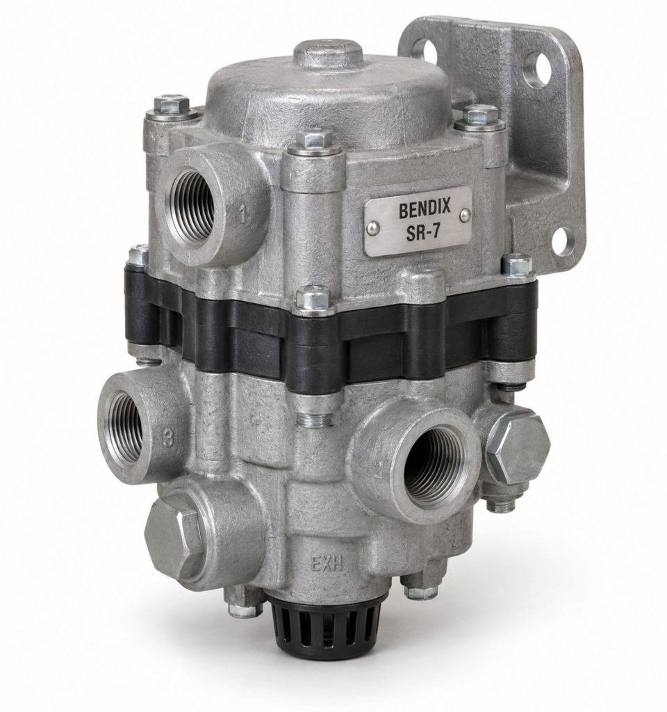
The Bendix SR-7 is a spring-brake modulating valve used with a dual-circuit air-brake system and combination spring-brake actuators. It controls air pressure within the spring-brake chambers during parking, emergency operation, and certain service-brake system failures.
During normal driving, compressed air holds the powerful mechanical springs inside the spring-brake actuators in the released position. When the driver applies the parking brakes, the SR-7 rapidly exhausts this hold-off pressure, allowing the springs to apply the rear foundation brakes.
If the primary service-brake circuit loses pressure, the SR-7 can use a service-brake signal from the remaining circuit to modulate the spring brakes. This provides a controlled braking response instead of allowing the spring brakes to apply suddenly at full force.
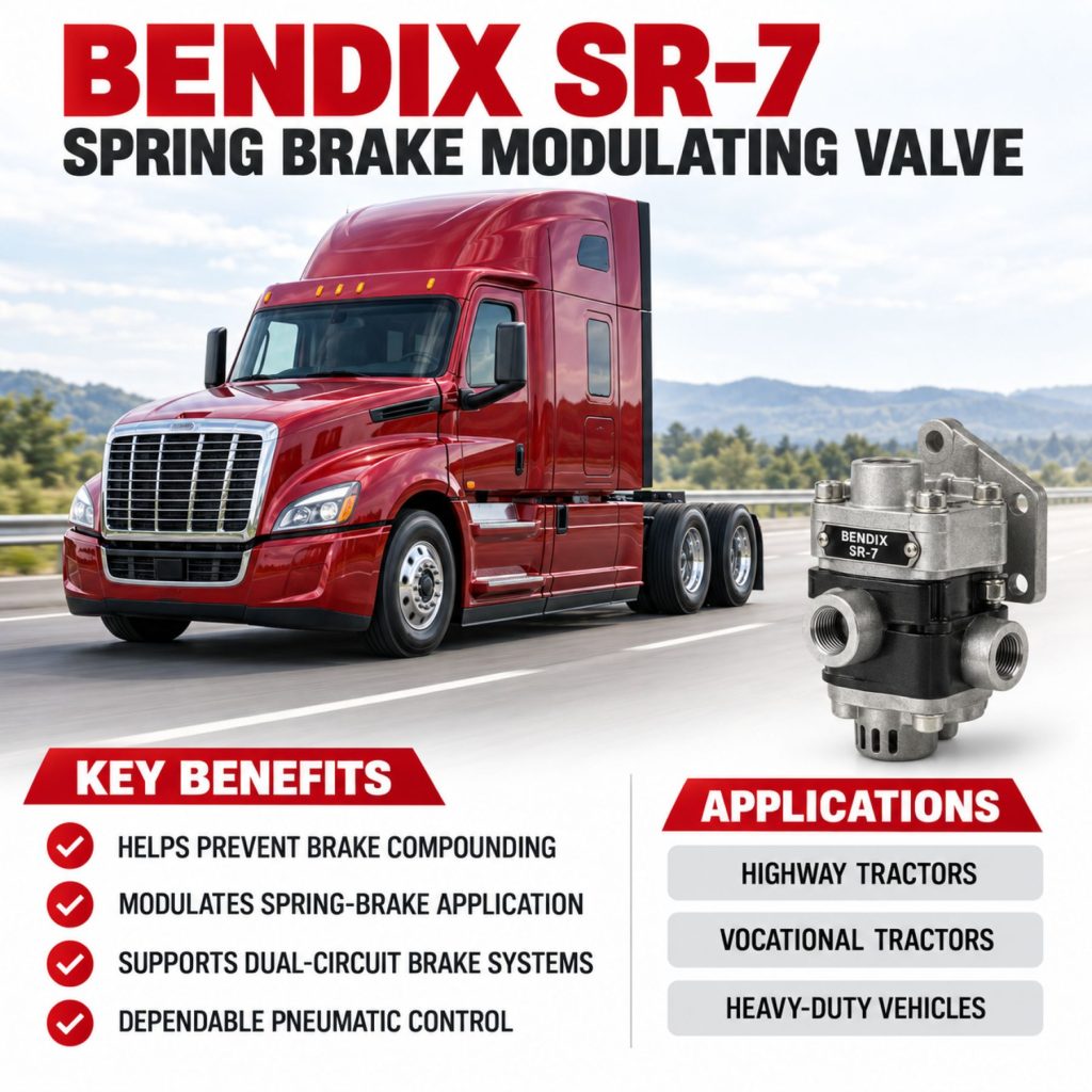
The valve also provides anti-compounding protection. This function helps prevent the service brakes and spring brakes from applying their full forces to the same foundation brake at the same time.
Key Characteristics
- Spring-brake control valve
- Designed for dual-circuit air-brake systems
- Works with combination spring-brake actuators
- Rapidly applies the spring brakes for parking
- Modulates spring-brake application during certain service-system failures
- Provides anti-compounding protection
- Receives parking and service control signals
- Distributes hold-off air to multiple spring-brake chambers
- Normally mounted near the rear axle
- Supports truck, tractor, bus, and specialty-vehicle applications
- Uses pneumatic rather than electronic control
- Available in application-specific port and fitting configurations
- Service replacement must match the original valve
Major Components
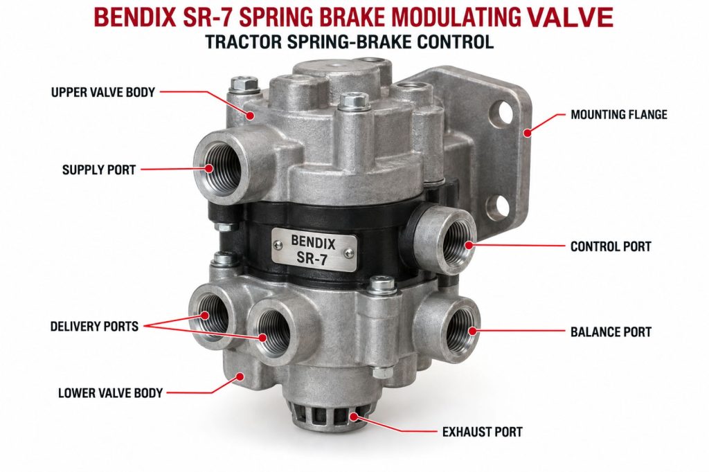
- Valve body
- Supply port
- Park-control port
- Service-control port
- Balance port
- Delivery ports
- Exhaust port
- Relay piston
- Modulating piston
- Inlet and exhaust valves
- Internal springs
- Check valve
- Valve seats
- Seals and O-rings
- Exhaust diaphragm or cover
- Mounting studs
- Air-line fittings
- Identification label or casting marks
How the Brake Component or System Works
The SR-7 controls the air pressure that holds the spring brakes in their released position.
During normal vehicle operation, air from the parking-brake control system enters the SR-7. The valve delivers air to the spring-brake sections of the combination actuators. This air compresses the mechanical power springs and keeps the parking brakes released.
When the driver pulls the parking-brake control, the control signal is exhausted. The SR-7 responds by rapidly releasing air from the spring-brake chambers. The mechanical springs then extend and apply the foundation brakes.
If the primary service-brake circuit fails, the SR-7 uses pressure from the remaining service circuit to proportionally exhaust air from the spring-brake chambers. As the driver increases the service-brake application, the valve allows the spring brakes to apply progressively.
The valve also responds to a service-brake application while the parking brakes are applied. It delivers air back to the spring-brake chambers in proportion to the service application, helping prevent excessive combined force at the foundation brakes.
Position and Function Within the Brake System
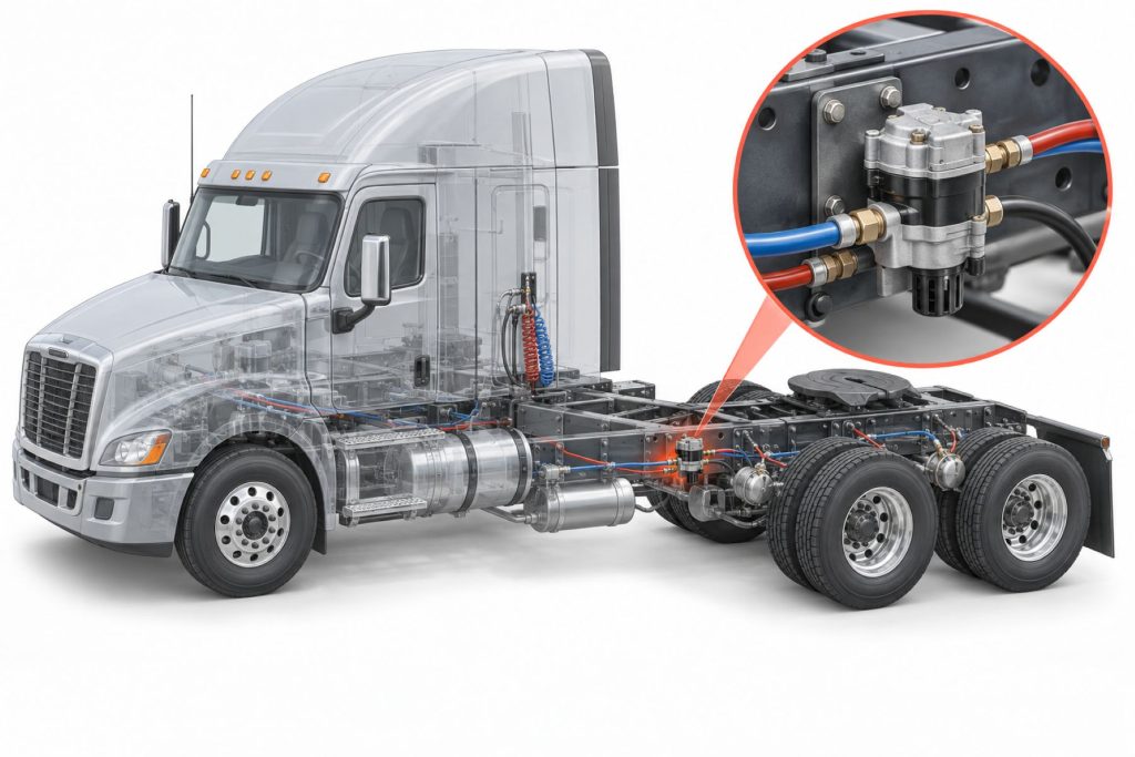
The SR-7 is typically mounted on a frame rail or crossmember near the vehicle’s rear axle and spring-brake actuators. Its location shortens the delivery lines between the valve and the rear brake chambers, helping the spring brakes apply and release promptly.
The valve communicates with several parts of the air-brake system:
- The supply reservoir provides compressed air.
- The parking control valve signals the SR-7 to release or apply the spring brakes.
- The service-brake circuit provides the signal used for emergency modulation and anti-compounding.
- The balance circuit coordinates valve response within the dual air system.
- The delivery ports direct hold-off air to the spring-brake chambers.
- The exhaust port releases air when the spring brakes are applied.
The exact plumbing arrangement depends on the vehicle manufacturer, model year, and brake-system configuration.
Common Specifications
- Valve Type: Pneumatic spring-brake modulating valve
- Brake-System Configuration: Dual-circuit air-brake system
- Actuator Type: Combination service and spring-brake chamber
- Mounting Position: Frame rail or crossmember near the rear axle
- Supply Port: Commonly 1/2-inch NPT, depending on part number
- Delivery Ports: Commonly 3/8-inch NPT, depending on part number
- Control and Balance Ports: Application-specific NPT or push-to-connect configurations
- Number of Delivery Ports: Multiple delivery ports for spring-brake actuator connections
- Normal Spring-Brake Hold-Off Pressure: Approximately 107 psi in applicable configurations
- Approximate Weight: 3.3 pounds
- Device Code: 9043
- Control Method: Pneumatic
- Electrical Connection: None on conventional SR-7 valves
Exact port sizes, fittings, pressure settings, mounting details, and internal configurations must be confirmed using the complete Bendix service or original-equipment part number.
Operating Specifications and Performance
The SR-7 must provide sufficient air pressure to hold the spring brakes fully released during normal vehicle operation. It must also exhaust that air promptly when the driver applies the parking brakes.
During a qualifying primary service-circuit failure, the valve reduces spring-brake hold-off pressure in proportion to the service-brake signal from the functioning circuit. For example, an increase in service control pressure produces a corresponding reduction in spring-brake chamber pressure.
Valve performance depends on:
- Adequate supply pressure
- Correct air-line connections
- Proper parking-control operation
- An intact service-control circuit
- Correct balance-port plumbing
- Unrestricted delivery lines
- Proper spring-brake chamber operation
- An unobstructed exhaust port
- Correct valve selection
A problem elsewhere in the air system can produce symptoms that appear to originate with the SR-7. The complete system should be tested before the valve is replaced.
Braking Performance and System Integration
The SR-7 works as part of the vehicle’s parking and emergency braking systems. It does not replace the foot brake valve, relay valves, ABS modulators, spring-brake chambers, or foundation brakes.
The valve supports three primary braking functions:
- Rapid spring-brake application when the vehicle is parked
- Proportional spring-brake modulation during certain service-circuit failures
- Prevention of excessive service-brake and spring-brake force compounding
Correct operation helps maintain controlled braking during a partial air-system failure. It also helps protect foundation-brake components from excessive mechanical loading when the parking and service brakes are used together.
The final braking force still depends on the condition and adjustment of the complete wheel-end system, including brake chambers, slack adjusters, pushrods, camshafts, brake shoes or pads, drums or rotors, and tires.
Air Supply, Controls, and Electronic Integration
The SR-7 is a pneumatic valve. It does not require a direct electrical connection or software programming.
The valve receives compressed air and control signals from the vehicle’s air-brake system. Its primary pneumatic connections include:
- Supply air
- Parking-control signal
- Service-control signal
- Balance signal
- Delivery air
- Exhaust
The SR-7 can operate on vehicles equipped with ABS, automatic traction control, or electronic stability control. Those electronic systems control service-brake pressure through separate modulators and controllers.
Although the SR-7 is not electronically controlled, its performance affects the same braking system. Incorrect plumbing, internal leakage, or delayed spring-brake operation can influence the vehicle’s overall parking and emergency braking behavior.
Installation, Adjustment, and Brake Balance
The replacement SR-7 must be mounted securely in the approved chassis location and connected according to the vehicle manufacturer’s air-brake diagram.
Installation requirements may include:
- Confirming every port before disconnecting air lines
- Tagging the original air lines
- Matching the original valve part number
- Using the correct mounting orientation
- Keeping the exhaust port unobstructed
- Supporting air lines to prevent vibration damage
- Using approved air-brake tubing and fittings
- Avoiding contamination inside open lines
- Tightening fittings without damaging the valve body
- Testing the completed system for leakage
- Performing parking, modulation, and anti-compounding tests
The SR-7 does not contain a normal external brake-balance adjustment. Brake balance depends on correct valve selection, system plumbing, chamber sizing, foundation-brake configuration, and vehicle engineering.
Technicians should not attempt to change braking behavior by installing a valve with an unapproved pressure setting or internal configuration.
Foundation Brake, Axle, and Wheel-End Compatibility
The SR-7 is primarily associated with rear axles equipped with combination spring-brake actuators. Depending on the vehicle, it may support a single drive axle, tandem drive axles, or another approved rear-axle arrangement.
The valve may be used with:
- S-cam drum brakes
- Air disc brakes
- Single rear axles
- Tandem drive axles
- Combination spring-brake chambers
- Automatic slack adjusters
- Antilock braking systems
- Traction-control systems
- Electronic stability-control systems
Compatibility depends on the complete brake-system design rather than the foundation-brake type alone. The number and size of the actuators, delivery-line arrangement, reservoir configuration, control-valve design, and original vehicle engineering must all be considered.
Common Applications
- Highway tractors
- Regional-haul tractors
- Heavy-duty straight trucks
- Dump trucks
- Concrete mixers
- Refuse trucks
- Roll-off trucks
- Tank trucks
- Utility trucks
- Recovery vehicles
- Municipal trucks
- School buses
- Transit buses
- Motor coaches
- Fire apparatus
- Vocational trucks
- Specialty commercial vehicles
- Vehicles with dual-circuit air brakes
- Vehicles with rear combination spring-brake actuators
Vehicle and Brake-System Compatibility
The SR-7 must match the vehicle’s original brake-system configuration.
Compatibility should be confirmed using:
- Vehicle manufacturer
- Vehicle identification number
- Model and model year
- Bendix valve part number
- Original equipment part number
- Port sizes
- Port locations
- Fitting types
- Mounting-stud arrangement
- Supply-pressure requirements
- Spring-brake chamber sizes
- Number of delivery circuits
- Foundation-brake type
- Vehicle air-system diagram
A valve should not be selected solely because it resembles the original SR-7. Similar-looking valves may have different ports, pressure settings, check-valve designs, or operating functions.
Advantages
- Rapid parking-brake application
- Controlled spring-brake modulation
- Anti-compounding protection
- Compatibility with dual-circuit air brakes
- Pneumatic operation
- No direct electrical connection
- Multiple spring-brake delivery ports
- Frame-mounted installation
- Support for drum and air disc brakes
- Compatibility with single and tandem rear axles
- Established use in commercial vehicles
- Serviceable air-brake system design
- Application-specific replacement options
Limitations or Considerations
- Requires correct air-line plumbing
- Must match the original part number
- Internal configurations may differ
- Port arrangements vary by application
- Air contamination can damage internal seals
- Restricted lines can delay operation
- An obstructed exhaust can affect spring-brake application
- Air-system leaks may imitate valve failure
- Incorrect installation can create unsafe braking behavior
- Requires complete system testing after replacement
- Does not correct worn spring-brake chambers
- Does not correct foundation-brake problems
- Does not directly control ABS or stability functions
- Must not be confused with trailer spring-brake valves
Driver and Operator Experience
The driver controls the spring brakes through the vehicle’s parking-brake control valve. The SR-7 performs its functions automatically in response to air pressure and brake-control signals.
During normal operation, the driver should notice:
- Full spring-brake release after adequate air pressure builds
- Prompt parking-brake application
- Normal vehicle movement after the parking brakes are released
- Stable system pressure
- No continuous air leakage near the rear axle
Conditions that should be reported include:
- Spring brakes that release slowly
- Spring brakes that fail to release completely
- Delayed parking-brake application
- Continuous air leakage
- Unexpected spring-brake application
- Vehicle movement with the parking control applied
- Brake dragging
- Low-air warnings
- Uneven rear braking
- Excessive compressor cycling
A vehicle with questionable parking or emergency brake operation should be removed from service until the cause is identified and corrected.
Maintenance and Ownership Notes
- Inspect the valve and mounting hardware.
- Check air lines for abrasion, cracking, and heat damage.
- Inspect fittings for leakage.
- Keep the exhaust port clean and unobstructed.
- Listen for air leakage with the brakes released and applied.
- Test parking-brake application and release.
- Test spring-brake modulation according to Bendix procedures.
- Verify anti-compounding operation.
- Inspect spring-brake chambers for leakage.
- Check pushrod movement.
- Inspect slack adjusters and foundation brakes.
- Drain reservoirs according to the maintenance schedule.
- Maintain the air dryer and compressor.
- Prevent dirt from entering disconnected air lines.
- Use the correct replacement valve and service kits.
- Perform a complete operational test after service.
Common Brake-System Problems
Spring brakes will not release: Insufficient reservoir pressure, restricted supply lines, incorrect parking-control signals, a blocked delivery line, internal valve leakage, or defective spring-brake chambers may be responsible.
Spring brakes release slowly: Possible causes include:
- Restricted air lines
- Damaged fittings
- Low supply pressure
- Contaminated internal valve components
- Incorrect valve installation
- Leaking spring-brake chambers
Spring brakes will not apply promptly: A restricted exhaust, incorrect control plumbing, damaged parking-control line, internal valve problem, or binding brake actuator may delay application.
Continuous air leakage from the exhaust: Possible causes include:
- Damaged internal seals
- Contaminated valve seats
- Defective inlet or exhaust valve
- Incorrect control pressure
- Air leaking through another connected component
- Internal spring-brake chamber leakage
Vehicle will not remain parked: Improper brake adjustment, weak or damaged power springs, incorrect chamber selection, worn foundation brakes, contaminated friction material, or an SR-7 control problem may be responsible.
Brakes drag after parking-brake release: Low hold-off pressure, a restricted delivery line, damaged spring-brake chamber, binding foundation brake, incorrect pushrod adjustment, or internal valve leakage may prevent complete release.
Improper emergency modulation: Possible causes include:
- Incorrect service-control connection
- Blocked balance line
- Internal valve damage
- Incorrect replacement valve
- Primary and secondary circuit plumbing problems
- Insufficient pressure in the functioning service circuit
Brake compounding: Incorrect plumbing, internal valve malfunction, blocked air lines, or installation of the wrong valve can prevent proper anti-compounding operation.
Safety and Service Precautions
Spring-brake actuators contain powerful mechanical springs capable of causing serious injury. The spring-brake chamber must never be disassembled unless the manufacturer specifically identifies it as serviceable and the proper procedures and equipment are used.
Before servicing the SR-7:
- Park the vehicle on a level surface.
- Apply approved wheel chocks.
- Secure the vehicle by means other than the air brakes.
- Shut down the engine.
- Remove the ignition key.
- Drain all air reservoirs.
- Verify that no air pressure remains.
- Identify every air line before disconnection.
- Wear appropriate eye protection.
- Follow Bendix and vehicle manufacturer procedures.
Never disconnect a pressurized air line. Escaping compressed air can cause personal injury and can propel dirt or other particles.
After service, test the parking brakes, spring-brake release, emergency modulation, anti-compounding function, air-pressure buildup, low-air warnings, and the entire system for leakage before returning the vehicle to operation.
Identification Information
Identification information may appear on a label, stamped plate, casting, mounting surface, or vehicle parts record.
Record the following:
- Bendix SR-7 model designation
- Complete Bendix service part number
- Original equipment part number
- Device code
- Vehicle identification number
- Vehicle manufacturer
- Model and model year
- Port sizes
- Port locations
- Fitting types
- Mounting-stud spacing
- Balance-port configuration
- Supply-port arrangement
- Number of delivery ports
- Spring-brake chamber sizes
- Foundation-brake type
Identification should be completed before air lines are disconnected. Photographs and individual line labels can help preserve the original plumbing arrangement.
Buying Considerations
- Confirm that the original valve is a Bendix SR-7.
- Record the complete Bendix part number.
- Match the original equipment cross-reference number.
- Compare every port location.
- Verify all port sizes.
- Confirm push-to-connect or threaded fittings.
- Match the mounting-stud arrangement.
- Verify the internal check-valve configuration.
- Confirm spring-brake chamber compatibility.
- Check the number of required delivery ports.
- Review new and remanufactured options.
- Determine whether fittings are included.
- Check whether unused ports require approved plugs.
- Verify warranty coverage.
- Purchase from a qualified heavy-duty brake supplier.
- Use a technician familiar with dual-circuit air-brake systems.
Variants and Configurations
- Different Bendix service part numbers
- Original equipment configurations
- Aftermarket service replacements
- Different supply-port arrangements
- Different control-port fittings
- Different balance-port configurations
- Multiple delivery-port arrangements
- Threaded NPT ports
- Push-to-connect fittings
- Application-specific mounting studs
- Internal check-valve configurations
- New valve assemblies
- Remanufactured valve assemblies
- Vehicle-specific replacement packages
Comparison to Similar Equipment
Compared with a conventional relay valve, the SR-7 performs specialized spring-brake functions, including emergency modulation and anti-compounding. A standard relay valve primarily speeds service-brake application and release.
Compared with the Bendix SR-5 trailer spring-brake valve, the SR-7 is used within a towing vehicle’s dual-circuit air system. The SR-5 is designed for trailer spring-brake control.
Compared with the Bendix SR-1 spring-brake valve, the SR-7 uses a different operating design and supports different vehicle air-system configurations. These valves should not be treated as interchangeable.
Compared with a simple quick-release valve, the SR-7 manages multiple control signals and provides much broader spring-brake control.
Best Fit For
- Vehicles originally equipped with the Bendix SR-7
- Trucks with dual-circuit air brakes
- Tractors with rear combination spring-brake actuators
- Single-drive-axle trucks
- Tandem-drive-axle trucks
- Highway tractors
- Vocational trucks
- Commercial buses
- Municipal vehicles
- Fire and emergency apparatus
- Vehicles requiring spring-brake modulation
- Vehicles requiring anti-compounding protection
- Fleets maintaining Bendix air-brake systems
Related Vehicle and Trailer Types
- Complete Guide to Semi Truck Types
- Class 6 vs Class 7 vs Class 8 Trucks
- Highway tractors
- Day cab tractors
- Sleeper tractors
- Heavy-duty straight trucks
- Dump trucks
- Concrete mixers
- Refuse trucks
- Tank trucks
- Recovery vehicles
- Commercial buses
- Fire apparatus
- Specialty commercial vehicles
Related Truck and Trailer Models
- Freightliner Cascadia
- Freightliner 114SD
- Freightliner 122SD
- Kenworth T680
- Kenworth T880
- Peterbilt 579
- Peterbilt 567
- Mack Anthem
- Mack Granite
- Volvo VNL
- Volvo VHD
- International HX Series
- Western Star 47X
- Western Star 49X
Related Brake System Types
- Brake Systems
- Air Brake Systems
- Drum Brake Systems
- Air Disc Brake Systems
- Brake Chambers & Actuators
- ABS & Electronic Braking Systems
- Trailer Brake Systems
- Parking-brake systems
- Emergency-brake systems
- Dual-circuit air-brake systems
- Spring-brake systems
- Pneumatic brake-control systems
Related Brake Products
- Bendix Tu-Flo 550 Air Compressor
- Bendix BA-921 Air Compressor
- Bendix AD-9 Air Dryer
- Bendix AD-HF Air Dryer
- Bendix ADB22X Air Disc Brake
- Bendix EverSure Spring Brake
- Bendix ESP Full Stability System
- Bendix SR-5 Trailer Spring Brake Valve
- Bendix SR-1 Spring Brake Valve
- Bendix MV-3 Dash Control Valve
- Bendix R-12 Relay Valve
- Bendix QR-1 Quick Release Valve
Related Equipment Systems
- Equipment Systems
- Suspension Systems
- Axles & Differentials
- Truck air compressors
- Air dryers
- Air reservoirs
- Rear axles
- Foundation brakes
- Air-suspension systems
- Vehicle electrical systems
- Trailer air systems
Related Guides
- Brake System Guides
- Air Brake Systems Explained
- Air Disc Brakes vs Drum Brakes
- How to Inspect and Maintain Commercial Truck Brakes
- Tractor vs Trailer Brake Systems
- How Truck ABS and Electronic Stability Control Work
- Commercial Truck Brake Components Explained
Regulatory and Compliance Notes
Commercial-vehicle parking and emergency brake systems must satisfy applicable federal, state, provincial, and local requirements. In the United States, vehicle manufacturers must certify applicable air-brake systems under Federal Motor Vehicle Safety Standard No. 121.
Replacing or modifying an SR-7 must not interfere with:
- Parking-brake application
- Parking-brake release
- Emergency brake modulation
- Anti-compounding operation
- Air-pressure buildup
- Low-air warning operation
- Primary and secondary circuit separation
- Required stopping performance
- ABS and stability-control operation
- Spring-brake chamber operation
Motor carriers must maintain brake components according to applicable inspection, repair, and maintenance regulations. A leaking, damaged, incorrectly installed, or improperly operating valve can place the vehicle out of service.
Real World Operating Notes
An SR-7 problem can resemble a defective spring-brake chamber, parking-control valve, relay valve, restricted air line, or low-pressure condition. A complete pneumatic test is more reliable than replacing components based only on symptoms.
Technicians should identify every air line before removing the original valve. Reversing the service, balance, supply, or parking-control connections can create dangerous and unpredictable brake operation.
Continuous exhaust leakage may originate in the SR-7, but air can also travel backward from another defective component. Isolating the connected circuits helps identify the actual source.
Brake drag following parking-brake release should be evaluated at both the valve and wheel ends. Even if full pressure reaches the spring-brake chambers, damaged actuators or binding foundation brakes may prevent complete release.
Frequently Asked Questions
What is the Bendix SR-7?
The Bendix SR-7 is a pneumatic spring-brake modulating valve used with dual-circuit air-brake systems and combination spring-brake actuators.
What are the SR-7 valve’s main functions?
It provides rapid parking-brake application, modulates the spring brakes during certain primary service-circuit failures, and helps prevent brake compounding.
Where is the SR-7 located?
It is commonly mounted on a frame rail or crossmember near the rear axle and spring-brake chambers.
What is spring-brake modulation?
Spring-brake modulation is the controlled reduction of hold-off pressure in the spring-brake chambers. This allows the mechanical springs to apply braking force progressively instead of immediately applying at full force.
What is brake compounding?
Brake compounding occurs when service-brake pressure and mechanical spring-brake force act on the same foundation brake simultaneously. Excessive combined force can damage brake components.
Does the SR-7 control ABS?
No. The SR-7 is pneumatically controlled. ABS and stability-control functions are managed by separate electronic controllers and pressure modulators.
Is the SR-7 used on trailers?
The SR-7 is primarily used within a towing vehicle’s dual-circuit air-brake system. Trailer spring-brake systems commonly use different valves, such as application-specific trailer spring-brake valves.
Why are the spring brakes slow to release?
Possible causes include low air pressure, restricted lines, valve contamination, incorrect plumbing, leaking brake chambers, or binding foundation brakes.
Why is air leaking from the SR-7 exhaust?
Air leakage may be caused by contaminated valve seats, damaged seals, internal valve damage, incorrect control pressure, or leakage through another connected brake component.
Are all SR-7 valves interchangeable?
No. Port sizes, fittings, pressure settings, check-valve arrangements, and original equipment specifications may differ.
How can the correct replacement valve be identified?
Use the complete Bendix part number, original equipment number, vehicle VIN, port arrangement, fitting types, mounting configuration, and vehicle air-system diagram.
Availability and Where to Find
Bendix SR-7 valves and service components may be available through Bendix distributors, commercial-truck dealerships, bus parts suppliers, heavy-duty brake specialists, fleet-maintenance providers, and commercial-vehicle parts retailers.
Availability may include:
- New SR-7 valve assemblies
- Remanufactured valve assemblies
- Application-specific replacement valves
- Internal service components
- Check-valve kits
- Sealing components
- Approved fittings
- Mounting hardware
Before ordering, confirm the complete Bendix part number, original equipment cross-reference, port arrangement, fitting type, mounting design, and internal check-valve configuration.
Current technical information, parts support, and distributor resources are available through Bendix Services and Support.
Support Trucking Families
Truck Equipment Atlas supports the mission of Grey Cross, a nonprofit dedicated to helping families of truck drivers who lose their lives while on the road. As the site grows, part of its mission is to bring awareness and support to these families.
Podcast or Video Section
Learn More Through Audio and Video
Truck Equipment Atlas will continue expanding with podcast episodes, interviews, and equipment breakdowns to help drivers and fleets better understand trucks and equipment.
Follow the Growth of Truck Equipment Atlas
Truck Equipment Atlas continues to expand with new truck profiles, trailer coverage, diesel engine pages, equipment system resources, manufacturer information, and educational guides.
Visit our Site Updates page to explore recent additions, project milestones, and upcoming resources as we continue building one of the industry’s growing commercial trucking equipment reference libraries.
View the Latest Site Updates: Truck Equipment Atlas Site Updates