
Brake Chambers & Actuators
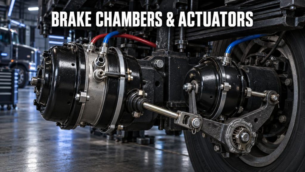
Commercial brake chambers and actuators convert compressed-air pressure into the mechanical force needed to apply a vehicle’s foundation brakes. They connect the pneumatic portion of the air-brake system with the mechanical components at each wheel.
Service chambers apply the brakes during normal driving. Combination spring-brake chambers add a powerful mechanical spring that provides parking and emergency-brake functions when air pressure is released.
Truck Equipment Atlas covers service chambers, spring brakes, air disc brake actuators, chamber sizes, stroke lengths, mounting configurations, inspection requirements, maintenance considerations, and individual products from major commercial braking manufacturers.
Brake Chambers and Actuators on Truck Equipment Atlas
Explore the commercial brake chambers and actuators being added to Truck Equipment Atlas:
Bendix
Haldex
Additional service chambers, combination spring brakes, air disc brake actuators, long-stroke chambers, severe-duty actuators, and related components will be added as the Truck Equipment Atlas Brake Systems Library continues to expand.
How Commercial Brake Chambers Work
When the driver presses the brake pedal, the air-brake system directs compressed air into the service side of the brake chamber.
The air pressure acts against a flexible diaphragm. As the diaphragm moves, it pushes a pressure plate and extends the chamber pushrod.
On an S-cam drum brake, the pushrod moves the slack adjuster. The slack adjuster rotates the camshaft, and the S-cam forces the brake shoes outward against the drum.
On an air disc brake, the actuator applies the caliper mechanism. The caliper presses the brake pads against the rotor.
When the driver releases the pedal, air exhausts from the chamber. The diaphragm and pushrod return to their released positions, allowing the foundation brake to release.
Major Brake Chamber and Actuator Components
A commercial brake chamber or actuator may include:
- Chamber housing
- Service diaphragm
- Pressure plate
- Return spring
- Pushrod
- Clevis
- Clevis pin
- Mounting studs
- Mounting nuts
- Clamp band
- Air inlet port
- Dust boot
- Drain opening
- Service chamber section
- Spring-brake section
- Power spring
- Release bolt or caging bolt
- Release tool
- Internal seals
- Breather system
- Protective plugs
- Identification markings
Exact components vary according to the chamber type, manufacturer, size, stroke, brake design, axle position, and vehicle application.
Service Brake Chambers
A service brake chamber uses compressed air to apply a foundation brake during normal vehicle operation.
Service-only chambers are commonly used on:
- Steer axles
- Non-parking auxiliary axles
- Certain trailer axles
- Specialty commercial vehicles
- Application-specific air-brake systems
A service chamber does not contain the large mechanical power spring used for parking and emergency braking.
Important service-chamber characteristics include:
- Chamber type
- Effective diaphragm area
- Maximum stroke
- Pushrod length
- Mounting-stud pattern
- Air-port location
- Clevis configuration
- Axle position
- Foundation-brake compatibility
- Operating environment
The chamber must be correctly matched to the brake, slack adjuster, camshaft, axle rating, and approved vehicle specification.
Combination Spring-Brake Chambers
A combination spring-brake chamber contains two primary sections:
- Service-brake chamber
- Spring-brake chamber
The service section uses compressed air to apply the brakes during normal driving.
The spring-brake section contains a powerful mechanical spring. Air pressure compresses and holds the spring during normal vehicle operation.
When the parking brake is applied, air is exhausted from the spring-brake section. The stored force of the power spring extends the pushrod and applies the foundation brake.
Combination spring brakes are commonly installed on:
- Drive axles
- Trailer axles
- Tag axles
- Pusher axles
- Certain specialty-vehicle axles
They provide service, parking, and emergency-brake functions within one assembly.
Spring-Brake Parking Operation
When the vehicle’s parking-brake control is pushed in, compressed air enters the spring-brake chambers and compresses the power springs. This releases the parking brakes.
When the control is pulled out, air exhausts from the chambers. The power springs expand and mechanically apply the brakes.
Spring brakes help hold the vehicle when parked without depending on a continuous air supply.
Parking performance depends on:
- Spring-brake chamber condition
- Available spring force
- Pushrod adjustment
- Foundation-brake condition
- Brake-drum or rotor condition
- Brake-lining or pad condition
- Tire traction
- Vehicle loading
- Road grade
- Correct control-valve operation
Spring brakes should not be treated as a substitute for proper parking procedures. Drivers should follow vehicle instructions and use wheel chocks when required.
Emergency-Brake Operation
If air pressure falls too low, the spring brakes may begin to apply automatically.
This creates an emergency function that does not depend on normal service-brake air pressure.
The exact application sequence depends on:
- Vehicle air-system design
- Spring-brake control valve
- Modulating valve
- Reservoir pressure
- Tractor-protection system
- Trailer emergency system
- Chamber configuration
- Applicable vehicle requirements
A sudden spring-brake application can affect vehicle stability. Drivers should respond immediately to low-air warnings before pressure falls to the point where the spring brakes begin applying.
Air Disc Brake Actuators
Air disc brakes use pneumatic actuators designed to apply the caliper mechanism.
Air disc brake actuators may include:
- Service-only actuators
- Combination service and spring-brake actuators
- Steer-axle actuators
- Drive-axle actuators
- Trailer actuators
- Application-specific mounting arrangements
The actuator must match the caliper, brake carrier, mounting interface, required output, stroke, axle position, and air-system design.
An actuator designed for an S-cam drum brake should not be assumed interchangeable with an air disc brake actuator.
Explore Air Disc Brake Systems for additional information.
Brake Chamber Sizes
Commercial brake chambers are identified by type or size designations related to their effective diaphragm area.
Common designations may include:
- Type 12
- Type 16
- Type 20
- Type 24
- Type 30
- Combination chamber sizes
- Application-specific actuator sizes
A larger effective diaphragm area generally produces more pushrod force at the same air pressure.
Increasing chamber size does not automatically improve the brake system. Installing a chamber with the wrong output can upset brake balance, overload foundation-brake components, change stroke requirements, or create clearance problems.
Replacement chambers should match the vehicle manufacturer’s or brake-system manufacturer’s approved specification.
Standard-Stroke and Long-Stroke Chambers
Commercial brake chambers may use standard-stroke or long-stroke designs.
Long-stroke chambers permit additional pushrod travel and commonly carry identification markings that distinguish them from standard-stroke chambers.
Identification may include:
- Chamber tags
- Embossed markings
- Colored identification bands
- Square air ports
- Model numbers
- Stroke information
- Manufacturer-specific markings
The allowable pushrod-stroke limit depends on the chamber type, size, and design.
A technician must correctly identify the chamber before determining whether its pushrod travel is within the applicable limit.
Standard-stroke and long-stroke chambers should not be mixed across an axle unless the configuration is specifically approved.
Pushrods and Clevises
The pushrod transfers force from the chamber to the foundation-brake mechanism.
On an S-cam drum brake, the pushrod connects to the slack adjuster through a clevis and clevis pin.
Important pushrod and clevis considerations include:
- Pushrod length
- Thread size
- Clevis type
- Clevis position
- Clevis-pin size
- Installed angle
- Chamber mounting
- Slack-adjuster alignment
- Available stroke
- Released position
Incorrect pushrod or clevis setup can change brake geometry and available stroke. It may cause poor braking, dragging brakes, excessive chamber travel, or automatic slack-adjuster problems.
Pushrods should not be shortened, lengthened, welded, or altered unless the procedure is specifically approved for the component and application.
Brake Chamber Stroke
Brake chamber stroke is the distance the pushrod travels from its released position to its applied position.
Excessive pushrod stroke may indicate:
- Worn brake linings
- Worn brake drum
- Incorrect brake adjustment
- Failed automatic slack adjuster
- Worn camshaft bushings
- Incorrect clevis position
- Damaged brake shoes
- Worn foundation-brake hardware
- Incorrect chamber installation
- Excessive component clearance
- Internal chamber problems
Brake stroke must be checked using the correct inspection procedure and compared with the limit for the identified chamber.
A chamber exceeding its allowable stroke can reduce braking force and may place the vehicle out of service.
Automatic Slack Adjusters
On an S-cam brake, the brake chamber works together with the automatic slack adjuster.
The slack adjuster converts linear pushrod movement into camshaft rotation. Its internal mechanism helps maintain the correct relationship between lining wear and pushrod stroke.
Repeatedly adjusting an automatic slack adjuster manually may hide an underlying problem involving:
- Brake chamber
- Pushrod
- Clevis
- Slack adjuster
- Camshaft
- Camshaft bushings
- Brake shoes
- Brake drum
- Return springs
- Foundation-brake geometry
The cause of excessive stroke should be diagnosed rather than repeatedly corrected through manual adjustment.
Spring-Brake Caging
Some spring-brake chambers can be mechanically released using a caging or release bolt.
Caging compresses the power spring so the brake can be released when normal air pressure is unavailable. This may be necessary for towing, recovery, or certain service operations.
Caging a spring brake:
- Does not repair the brake system
- Disables the parking force from that chamber
- May reduce emergency-braking capability
- Should only be performed by qualified personnel
- Requires approved procedures
- Requires control of vehicle movement
- May require wheel chocks
- Must be reversed before normal operation
A vehicle should not return to service with a spring brake caged unless specifically allowed under an approved repair or movement procedure.
Spring-Brake Safety
The power spring inside a spring-brake chamber stores enough mechanical energy to cause severe injury.
Important safety considerations include:
- Do not disassemble a sealed spring-brake chamber
- Do not loosen the spring-side clamp band
- Do not cut into the chamber
- Do not strike or heat the chamber
- Follow approved caging procedures
- Secure the vehicle against movement
- Release stored air pressure safely
- Replace damaged chambers using approved procedures
- Use correct tools and protective equipment
- Follow manufacturer instructions
Some chambers are permanently sealed to prevent service access to the power spring. These assemblies should be replaced rather than opened.
Chamber Mounting and Alignment
Brake chambers must be securely mounted and correctly aligned with the foundation-brake mechanism.
Important mounting considerations include:
- Correct mounting bracket
- Mounting-stud spacing
- Proper nut torque
- Pushrod alignment
- Clevis alignment
- Slack-adjuster angle
- Air-port orientation
- Drain-hole orientation
- Suspension clearance
- Axle clearance
- Wheel clearance
- Air-line clearance
- Protection from road debris
A chamber mounted at the wrong angle may create side loading, binding, rapid wear, reduced stroke, or interference with surrounding components.
Air Lines and Connections
Compressed air reaches the chamber through flexible hoses or air lines.
Lines and fittings should be inspected for:
- Air leakage
- Abrasion
- Cracking
- Heat damage
- Kinking
- Improper routing
- Loose fittings
- Corrosion
- Road-debris damage
- Suspension interference
- Tire interference
- Exhaust-system clearance
- Correct port connection
Air lines must have enough flexibility and clearance to accommodate axle and suspension movement without stretching, rubbing, or becoming pinched.
Chamber Corrosion and Contamination
Brake chambers operate in an environment exposed to water, road salt, dirt, mud, temperature changes, and vibration.
Potential concerns include:
- Housing corrosion
- Clamp-band corrosion
- Damaged paint or coating
- Contaminated breather openings
- Torn dust boots
- Water intrusion
- Damaged seals
- Rusted mounting studs
- Corroded air fittings
- Internal diaphragm damage
Severe corrosion can weaken the chamber housing or mounting components. A damaged or heavily corroded chamber should be evaluated according to manufacturer procedures and replaced when necessary.
Steer-Axle Brake Chambers
Steer axles commonly use service-only brake chambers because parking brakes are generally applied at other axle positions.
Steer-axle chamber considerations include:
- Left-to-right chamber matching
- Chamber size
- Pushrod length
- Slack-adjuster length
- Brake size
- Axle rating
- Steering clearance
- Suspension clearance
- Air-line routing
- Brake balance
Mismatched steer-axle chambers can cause unequal braking force and vehicle pull during a stop.
Drive-Axle Spring Brakes
Drive axles commonly use combination spring-brake chambers.
These chambers provide:
- Service-brake application
- Parking-brake application
- Emergency-brake capability
- Mechanical brake application when parking air is released
Drive-axle chambers must match the foundation brakes, axle ratings, suspension, wheels, tires, and complete vehicle braking system.
On tandem-drive vehicles, all chambers across the axle group should be inspected for matching type, size, stroke, condition, and installation.
Trailer Spring Brakes
Commercial trailers commonly use combination spring-brake chambers on their axles.
Trailer spring brakes apply when:
- The driver operates the trailer parking-brake control
- Trailer supply air is intentionally released
- The trailer is disconnected
- Supply-line pressure is lost
- The emergency system activates
Important trailer considerations include:
- Chamber size
- Chamber stroke
- Axle position
- Suspension movement
- Slider clearance
- Air-line routing
- Trailer ABS components
- Relay emergency valve operation
- Foundation-brake condition
- Tractor-trailer brake balance
Explore Trailer Brake Systems for additional information.
Highway Applications
Highway tractors and trailers require dependable chamber operation across high-mileage service.
Important highway considerations can include:
- Chamber durability
- Corrosion resistance
- Diaphragm life
- Spring life
- Pushrod-stroke control
- Brake balance
- Weight
- Air-line protection
- Replacement-parts availability
- Inspection access
- Maintenance intervals
- Vehicle downtime
Road salt, moisture, vibration, and temperature changes can affect chamber life even when the vehicle primarily operates on paved highways.
Vocational and Severe-Duty Applications
Vocational vehicles may expose brake chambers to harsh operating conditions.
Common applications include:
- Dump trucks
- Refuse trucks
- Concrete mixers
- Construction trucks
- Logging trucks
- Heavy-haul tractors
- Utility trucks
- Municipal vehicles
- Snowplows
- Oilfield trucks
- Mining vehicles
- Fire apparatus
- Recovery vehicles
- Severe-service equipment
These applications may expose chambers to mud, water, road salt, stone impacts, extreme articulation, high temperatures, frequent brake applications, and corrosive material.
Severe-duty applications may require enhanced corrosion protection, reinforced components, specialized breathers, protective shields, or more frequent inspections.
Advantages of Commercial Brake Chambers and Actuators
Depending on their design and application, commercial brake chambers can provide:
- Effective conversion of air pressure into braking force
- Service-brake operation
- Spring-applied parking brakes
- Emergency-brake capability
- Multiple chamber sizes
- Standard- and long-stroke options
- Drum-brake compatibility
- Air disc brake compatibility
- Steer, drive, auxiliary, and trailer applications
- Broad commercial-vehicle availability
- Replaceable modular components
- Integration with modern air-brake controls
- Established inspection procedures
The actual performance depends on correct chamber selection, installation, adjustment, maintenance, foundation-brake condition, and air-system operation.
Brake Chamber Limitations and Considerations
No single brake chamber is appropriate for every commercial vehicle.
Important considerations include:
- Chamber type
- Chamber size
- Maximum stroke
- Pushrod length
- Clevis configuration
- Mounting pattern
- Air-port location
- Foundation-brake compatibility
- Axle position
- Brake balance
- Spring-brake force
- Corrosion protection
- Suspension clearance
- Air-line routing
- Inspection access
- Replacement-parts compatibility
- Vehicle duty cycle
- Operating environment
Incorrect chamber selection or installation can change brake output, pushrod travel, adjustment, balance, and vehicle stopping performance.
Driver and Operator Considerations
Drivers should understand the vehicle’s service-brake, parking-brake, and low-air warning systems.
Warning signs can include:
- Audible air leakage
- Slow brake release
- Parking brake failing to release
- Parking brake failing to hold
- Vehicle pulling during braking
- Increased stopping distance
- Low air pressure
- Frequent compressor cycling
- Brake warning lamps
- Excessive pushrod movement
- Damaged or hanging chamber
- Loose air lines
- Burning odor
- Excessive wheel-end heat
Changes in brake operation should be reported immediately. A chamber or spring-brake problem can affect service, parking, and emergency-brake performance.
Maintenance and Ownership
Commercial brake chambers and actuators require regular inspection.
Important maintenance areas can include:
- Chamber housing
- Spring-brake housing
- Clamp bands
- Mounting studs
- Mounting brackets
- Mounting-nut torque
- Air ports
- Air lines and fittings
- Service diaphragm
- Pushrod
- Pushrod stroke
- Pushrod alignment
- Clevis
- Clevis pin
- Return operation
- Spring-brake release
- Caging hardware
- Drain openings
- Breather system
- Corrosion protection
- Foundation-brake adjustment
- Slack-adjuster operation
Maintenance requirements vary between manufacturers, chamber models, brake types, axle positions, duty cycles, and operating environments. Owners and technicians should follow the procedures and limits specified for the exact chamber and vehicle.
Choosing a Commercial Brake Chamber or Actuator
Selecting a brake chamber requires identifying the complete brake and vehicle configuration.
Important factors include:
- Truck or trailer application
- Vehicle manufacturer
- Model and model year
- Axle manufacturer
- Axle model
- Axle position
- Foundation-brake type
- Drum or air disc brake
- Brake size
- Chamber type
- Chamber size
- Standard or long stroke
- Maximum stroke
- Pushrod length
- Clevis type
- Mounting-stud pattern
- Air-port location
- Spring-brake requirements
- Slack-adjuster compatibility
- Suspension clearance
- Wheel and tire clearance
- Operating environment
- Manufacturer part number
- Replacement-parts availability
There is no single best brake chamber for every commercial vehicle. The correct unit is one properly matched to the foundation brake, axle, mounting arrangement, air system, suspension, and approved vehicle specification.
Related Brake System Categories
Explore additional brake-system categories:
- Air Brake Systems
- Air Disc Brake Systems
- Drum Brake Systems
- ABS & Electronic Braking Systems
- Trailer Brake Systems
- Brake System Guides
Related Brake System Guides
- Air Brake Systems Explained
- Air Disc Brakes vs Drum Brakes
- How to Inspect and Maintain Commercial Truck Brakes
- Tractor vs Trailer Brake Systems
- How Truck ABS and Electronic Stability Control Work
- Commercial Truck Brake Components Explained
Related Truck Equipment Resources
- Commercial Trucks
- Commercial Trailers
- Brake Systems
- Air Brake Systems
- Axles & Differentials
- Suspension Systems
- Tires & Wheels
- Equipment Systems
Understanding how the brake chamber, actuator, pushrod, slack adjuster, foundation brake, air valves, axle, suspension, wheel end, tires, vehicle loading, and driver controls work together is essential when evaluating commercial brake chambers and actuators.
Explore the Complete Brake Systems Library
Brake chambers and actuators represent one part of the larger commercial braking-equipment landscape.
Visit the Truck Equipment Atlas Brake Systems Library to explore air brake systems, air disc brakes, drum brakes, brake chambers and actuators, ABS and electronic braking systems, trailer brake systems, individual equipment profiles, and educational guides.
Additional service chambers, spring brakes, air disc brake actuators, chamber technologies, manufacturers, historical products, and educational resources will be added as Truck Equipment Atlas continues to expand.