
Commercial Truck Brake Components Explained
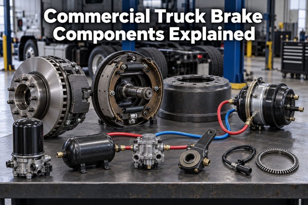
Commercial truck and trailer brake systems use pneumatic, mechanical, and electronic components to control vehicle speed, stop heavy loads, hold parked equipment, and help maintain stability during emergency or low-traction conditions.
Most heavy commercial vehicles use compressed air to operate their foundation brakes. The system must produce compressed air, remove moisture and contaminants, store air, control brake applications, transfer air pressure to each axle, convert that pressure into mechanical force, and apply friction at the wheel ends.
Modern trucks also use antilock braking systems, traction control, electronic stability control, and other electronic technologies to monitor wheel movement and regulate brake pressure.
This guide explains the major components found throughout commercial truck and trailer brake systems and describes how they work together.
The Complete Commercial Truck Brake System
A commercial air-brake system can be divided into five major sections:
- Air production
- Air treatment and storage
- Brake control and distribution
- Brake actuation
- Foundation braking
Electronic braking components operate across these sections by monitoring wheel and vehicle behavior and controlling brake pressure.
A simplified system follows this sequence:
Air Compressor → Air Dryer → Reservoirs → Brake Valve → Relay and Control Valves → Brake Chambers → Foundation Brakes
On a tractor-trailer combination, supply air and control signals also pass between the tractor and trailer.
Commercial Truck Brake Component Overview
| System Area | Major Components | Primary Function |
|---|---|---|
| Air production | Compressor and governor | Produce and regulate compressed air |
| Air treatment | Air dryer, purge valve, and filters | Remove moisture, oil, and contamination |
| Air storage | Supply, primary, secondary, and trailer reservoirs | Store compressed air |
| Driver control | Foot valve and parking-brake controls | Control service and parking brakes |
| Air distribution | Relay, quick-release, protection, and check valves | Route and control air pressure |
| Tractor-trailer connections | Service line, supply line, gladhands, and electrical cable | Connect tractor and trailer systems |
| Brake actuation | Service and spring-brake chambers | Convert air pressure into mechanical force |
| Foundation brakes | Air disc or S-cam drum brakes | Create friction at the wheel ends |
| Electronic control | ECU, sensors, modulators, and warning lamps | Control wheel slip and vehicle stability |
The exact equipment varies according to the truck, trailer, axle configuration, brake design, and application.
Air Production Components
Air Compressor
The air compressor produces the compressed air used by the Air Brake System.
On conventional diesel-powered trucks, the compressor is normally driven by the engine. Electrified commercial vehicles may use electrically driven compressors.
The compressor draws in air, compresses it, and sends it toward the air dryer and reservoirs.
Potential compressor problems include:
- Slow pressure build-up
- Excessive oil passing into the air system
- Unusual noise
- Air leakage
- Excessive cycling
- Overheating
- Drive-system failure
- Restricted intake
- Internal wear
A compressor must produce enough air to operate the brakes and other air-powered equipment without allowing system pressure to fall below safe operating levels.
Compressor Governor
The governor controls when the compressor loads and unloads.
When reservoir pressure falls to the system’s cut-in level, the governor signals the compressor to begin pumping air.
When pressure reaches the cut-out level, the governor causes the compressor to unload.
A defective governor may cause:
- Excessive system pressure
- Insufficient pressure
- Frequent compressor cycling
- Failure to build air
- Delayed compressor response
- Air-dryer purge problems
Operating-pressure specifications depend on the vehicle and air-system design.
Compressor Discharge Line
The discharge line carries hot compressed air from the compressor to the air dryer or supply reservoir.
Because compressed air leaving the compressor can be hot and contain moisture or oil vapor, the discharge line must tolerate heat, pressure, and vibration.
Inspect it for:
- Cracks
- Leaks
- Loose fittings
- Carbon buildup
- Kinks
- Heat damage
- Unsupported sections
- Contact with other components
A restricted discharge line can interfere with pressure build-up and compressor operation.
Air Treatment Components
Air Dryer
The air dryer removes moisture, oil, and other contaminants before compressed air reaches the main reservoirs.
The dryer helps protect:
- Reservoirs
- Brake valves
- Air lines
- ABS modulators
- Brake chambers
- Suspension components
- Other air-operated equipment
Most modern air dryers use a replaceable desiccant cartridge.
Common air-dryer components include:
- Desiccant cartridge
- Purge valve
- Heater
- Check valve
- Pressure-control components
- Mounting bracket
- Air connections
Desiccant Cartridge
The desiccant cartridge contains material that captures moisture and contaminants from compressed air.
As the vehicle operates, the dryer periodically regenerates or purges accumulated moisture.
A saturated or damaged cartridge may allow excessive moisture into the air system.
Service intervals vary according to:
- Compressor condition
- Climate
- Vehicle mileage
- Operating hours
- Air demand
- Vocational application
- Manufacturer recommendations
Purge Valve
The purge valve opens during the air-dryer purge cycle.
It releases accumulated moisture, oil, and contamination from the dryer.
Potential purge-valve problems include:
- Constant air leakage
- Failure to purge
- Ice formation
- Contamination
- Damaged seals
- Heater problems
- Incorrect cycling
A brief release of air during a normal purge event is expected. Continuous leakage requires inspection.
Air-Dryer Heater
The heater helps prevent moisture inside the purge-valve area from freezing.
A failed heater can contribute to air-dryer problems during cold weather.
Inspect the heater circuit for:
- Electrical power
- Ground condition
- Damaged wiring
- Corroded connectors
- Blown protection devices
- Physical damage
Air Storage Components
Supply Reservoir
The supply reservoir is the first reservoir to receive compressed air after it passes through the air dryer.
It is sometimes called the wet tank because moisture or contamination that passes beyond the dryer may collect there first.
The supply reservoir feeds other air-system circuits through protective valves.
Primary Reservoir
The primary reservoir commonly supplies one portion of the service-brake system, often including the rear or drive-axle brakes.
The exact arrangement varies by vehicle.
Secondary Reservoir
The secondary reservoir supplies another portion of the service-brake system, commonly including the steer-axle brakes.
Separating the system into primary and secondary circuits provides redundancy if one circuit develops a major leak or failure.
Trailer Reservoir
The trailer receives compressed air from the tractor and stores it in one or more trailer reservoirs.
Stored trailer air is used to:
- Apply the trailer service brakes
- Release the trailer spring brakes
- Support emergency operation
- Supply trailer air-operated equipment where applicable
The trailer reservoir allows nearby air to reach the brake chambers without traveling from the tractor during every brake application.
Reservoir Drain Valve
Drain valves allow moisture, oil, and contamination to be removed from air reservoirs.
Vehicles may use:
- Manual drain valves
- Cable-operated drain valves
- Automatic drain valves
- Heated automatic drain systems
Unexpected accumulation of oil or water may indicate an air-dryer, compressor, or maintenance problem.
Safety Valve
A safety valve protects the air system against excessive pressure.
If pressure rises beyond the valve’s setting, the valve opens to release air.
A safety valve that releases repeatedly can indicate a governor, compressor-unloader, or pressure-control problem.
Check Valve
A check valve allows air to flow in one direction while preventing reverse flow.
Check valves help isolate reservoirs and preserve air pressure if another part of the system develops a leak.
A leaking or stuck check valve can reduce system redundancy.
Driver-Control Components
Brake Pedal and Foot Valve
The brake pedal operates the foot valve, also called the treadle valve.
The foot valve controls the air pressure used for normal service-brake applications.
When the driver presses the pedal:
- The valve meters air toward the tractor brake circuits
- A service-control signal is sent to the trailer
- Brake pressure generally increases with pedal input
When the driver releases the pedal, the valve exhausts control pressure so the brakes can release.
Potential foot-valve problems include:
- Internal leakage
- External leakage
- Binding
- Delayed application
- Slow release
- Uneven circuit pressure
- Contamination
Parking-Brake Control
The parking-brake control is commonly represented by a yellow dashboard knob.
Pulling the control releases air from applicable tractor spring-brake chambers, allowing mechanical springs to apply the brakes.
Pushing the control supplies air to release the spring brakes when adequate system pressure is available.
The parking control should not be treated as a substitute for proper wheel chocks during maintenance.
Trailer Air-Supply Control
The trailer air-supply control is commonly represented by a red dashboard knob.
It controls supply air to the trailer.
When supply air is delivered:
- Trailer reservoirs charge
- Trailer spring brakes can release
- The trailer becomes ready for service-brake operation
When the control is pulled, supply air is removed and the trailer spring brakes apply.
Control design and behavior vary by vehicle.
Trailer Hand Control
Some tractors include a hand-operated trailer service-brake control.
It allows the driver to apply the trailer service brakes independently for limited operational checks or manufacturer-approved uses.
The hand control does not serve as a dependable parking brake because the trailer service brakes release when control pressure is removed.
Air-Control and Distribution Valves
Relay Valve
A relay valve reduces the time needed to apply brakes located far from the foot valve.
It receives a control signal and delivers air from a nearby reservoir to the brake chambers.
Relay valves are commonly used on:
- Tractor drive axles
- Trailer axles
- Long-wheelbase trucks
- Multi-axle vehicles
Potential problems include:
- Delayed application
- Slow release
- Air leakage
- Brake drag
- Contamination
- Internal sticking
- Incorrect valve selection
Quick-Release Valve
A quick-release valve allows air to exhaust near the brake chambers instead of returning through a long air line.
This helps brakes release more quickly.
A restricted or damaged valve can cause slow brake release or dragging brakes.
Double-Check Valve
A double-check valve allows air from either of two sources to reach a common circuit while preventing the sources from feeding directly into each other.
It is used where multiple controls may operate the same brake circuit.
Pressure-Protection Valve
A pressure-protection valve prevents an auxiliary circuit from consuming air until the primary brake system reaches a specified pressure.
These valves can supply:
- Air suspension
- Air seats
- Accessories
- Auxiliary equipment
- Trailer circuits
A defective valve may prevent an accessory circuit from charging or allow a leak to reduce protected brake-system pressure.
Inversion Valve
An inversion valve is used in certain spring-brake and emergency-brake circuits.
It can use pressure from one circuit to control spring-brake application if another service-brake circuit loses pressure.
Its exact operation depends on the vehicle’s air-system design.
Anti-Compounding Valve
An anti-compounding valve helps prevent the service brakes and spring brakes from applying their full forces simultaneously at the same wheel end.
Without anti-compounding protection, combined forces could overstress foundation-brake components.
Anti-compounding functions may be incorporated into another valve rather than installed as a separate component.
Tractor-Protection Valve
The tractor-protection valve helps preserve tractor air pressure if the trailer separates or a trailer air line develops a major leak.
When activated, it isolates the tractor from the trailer air circuits.
This allows the tractor to retain braking capability rather than losing its entire air supply through a failed trailer connection.
Trailer Relay Emergency Valve
The trailer relay emergency valve performs both service and emergency functions.
Depending on the system, it can:
- Control trailer reservoir charging
- Relay the tractor’s service-brake signal
- Deliver reservoir air to the trailer chambers
- Protect stored trailer air
- Respond to supply-pressure loss
- Support trailer spring-brake application
Learn more in Tractor vs Trailer Brake Systems.
Air Lines and Connections
Air Tubing
Air tubing carries compressed air between components.
Commercial vehicles may use:
- Flexible rubber hose
- Nylon air-brake tubing
- Reinforced hose
- Coiled tractor-trailer lines
- Metal tubing in certain locations
Inspect air lines for:
- Cracks
- Abrasion
- Kinks
- Heat damage
- Loose fittings
- Improper repairs
- Contact with moving parts
- Missing support clips
- Excessive stretching
- Air leakage
Fittings
Fittings connect air lines to valves, reservoirs, chambers, and other components.
Common problems include:
- Loose connections
- Damaged threads
- Cracked bodies
- Incorrect fittings
- Contaminated sealing surfaces
- Improper installation
- Air leakage
Only components approved for commercial air-brake service should be used.
Gladhands
Gladhands connect the tractor’s air lines to the trailer.
There is normally one connection for:
- Trailer supply air
- Trailer service control
Gladhand seals must create an airtight connection while allowing the tractor and trailer to disconnect.
Inspect for:
- Worn seals
- Cracks
- Corrosion
- Dirt
- Ice
- Loose connections
- Incorrect coupling
- Air leakage
Trailer Supply Line
The trailer supply line delivers compressed air from the tractor to the trailer reservoirs and helps keep the trailer spring brakes released.
It is also commonly called the emergency line.
Trailer Service Line
The service line carries the driver’s brake-control signal from the tractor to the trailer.
The trailer relay valve uses that signal to determine how much reservoir air to send to the trailer brake chambers.
Brake Chambers and Actuators
Brake Chambers and Actuators convert compressed-air pressure into mechanical force.
Service Brake Chamber
A service chamber contains a flexible diaphragm.
When compressed air enters:
- Air pressure pushes against the diaphragm.
- The diaphragm moves a pressure plate.
- The pressure plate moves the pushrod.
- The pushrod operates the foundation brake.
When air pressure is released, an internal return spring moves the diaphragm and pushrod back toward their released positions.
Spring-Brake Chamber
A spring-brake chamber contains a powerful mechanical spring in addition to the service-brake section.
Compressed air holds the power spring in the released position during normal operation.
When parking-brake air is released, the spring applies the brake mechanically.
Spring brakes provide:
- Parking braking
- Emergency application during major pressure loss
- Mechanical brake application without continuous air pressure
A spring-brake chamber must not be disassembled unless it is specifically designed for service and the approved procedure is followed.
Combination Brake Chamber
A combination chamber combines:
- A service-brake chamber
- A spring-brake chamber
It is commonly installed on tractor drive axles and trailer axles.
The service section responds to the brake pedal. The spring section applies the parking or emergency brake.
Brake-Chamber Diaphragm
The diaphragm separates the pressurized side of the chamber from the mechanical pushrod assembly.
A damaged diaphragm can cause:
- Air leakage
- Weak brake application
- Pressure loss
- Delayed response
- Inoperative brakes
Pushrod
The pushrod transfers movement from the chamber to the foundation-brake mechanism.
On a drum brake, it commonly connects to an automatic slack adjuster.
On an air disc brake, the chamber operates the caliper-actuation mechanism.
Pushrods should be inspected for:
- Bending
- Misalignment
- Damage
- Excessive stroke
- Improper length
- Loose connections
Clevis and Clevis Pin
A clevis connects the pushrod to the slack adjuster on many drum-brake systems.
The clevis pin allows movement at the connection.
Inspect for:
- Wear
- Missing retainers
- Elongated holes
- Corrosion
- Incorrect installation
- Excessive looseness
Worn linkage can contribute to lost motion and inconsistent brake operation.
S-Cam Drum-Brake Components
Drum Brake Systems commonly use an S-cam mechanism.
Automatic Slack Adjuster
The automatic slack adjuster transfers pushrod movement to the camshaft and helps maintain the correct clearance between the linings and drum.
Its functions include:
- Converting linear pushrod motion into camshaft rotation
- Maintaining foundation-brake clearance
- Providing mechanical leverage
- Supporting brake-stroke control
An automatic slack adjuster that repeatedly requires manual adjustment usually indicates an underlying problem.
Camshaft
The camshaft carries rotational movement from the slack adjuster to the S-cam head.
It passes through bushings and support brackets mounted at the wheel end.
Worn camshafts or bushings can cause:
- Excessive movement
- Uneven lining wear
- Increased stroke
- Poor brake release
- Reduced braking consistency
S-Cam
The S-cam head is shaped to push two brake shoes outward when the camshaft rotates.
The shoes then press their friction linings against the inside of the brake drum.
Wear at the S-cam, rollers, or supporting components can change brake geometry and reduce performance.
Camshaft Bushings
Bushings support the camshaft and allow it to rotate.
They require inspection for wear, lubrication condition, and excessive movement.
Brake Spider
The brake spider is the structural mounting plate for the drum-brake assembly.
It supports components such as:
- Brake shoes
- Anchor pins
- Camshaft brackets
- Dust shields
- Return springs
A cracked, bent, or loose spider can affect brake alignment.
Brake Shoes
Brake shoes are curved metal supports that carry the friction linings.
During application, the S-cam pushes the shoes outward toward the brake drum.
Shoes should be inspected for:
- Cracks
- Distortion
- Worn contact areas
- Damaged anchor points
- Incorrect installation
- Loose friction material
Friction Linings
Friction linings create braking force by contacting the inside of the drum.
Inspect linings for:
- Insufficient thickness
- Cracks
- Missing sections
- Contamination
- Heat damage
- Glazing
- Separation
- Uneven wear
- Exposed rivets
Brake Rollers
Rollers transfer force from the S-cam to the brake shoes.
Worn, seized, missing, or incorrectly installed rollers can interfere with brake application and release.
Return Springs
Return springs pull the brake shoes away from the drum when the service brakes are released.
Weak, stretched, broken, or missing springs can contribute to brake drag.
Anchor Pins
Anchor pins support and locate the brake shoes.
Wear or corrosion can interfere with shoe movement and alignment.
Brake Drum
The brake drum rotates with the wheel.
When the brake shoes expand, their linings contact the drum’s inner surface and create friction.
Drums should be inspected for:
- Cracks
- Excessive diameter
- Heat checking
- Scoring
- Grooves
- Hard spots
- Distortion
- Contamination
- Missing material
Air Disc Brake Components
Air Disc Brake Systems use calipers to clamp pads against rotating rotors.
Brake Caliper
The caliper surrounds part of the rotor and contains the mechanism that applies the brake pads.
When the chamber operates the caliper:
- The internal mechanism moves the inboard pad toward the rotor.
- Caliper movement brings the outboard pad into contact.
- Both pads clamp the rotor.
- Friction slows the wheel.
Calipers should be inspected for:
- Restricted movement
- Cracks
- Corrosion
- Air-chamber alignment
- Damaged seals
- Uneven pad wear
- Loose mounting
- Internal adjuster problems
Caliper Carrier or Torque Plate
The carrier supports the caliper and connects it to the axle or steering-knuckle assembly.
It must withstand the braking forces transferred from the caliper.
Loose or damaged mounting hardware can create serious braking problems.
Brake Pads
Brake pads contain friction material attached to metal backing plates.
They contact both sides of the rotor.
Inspect pads for:
- Insufficient thickness
- Uneven wear
- Cracking
- Missing friction material
- Contamination
- Heat damage
- Incorrect installation
- Damaged retainers
Brake Rotor
The rotor rotates with the wheel hub.
Brake pads clamp against its two friction surfaces.
Inspect rotors for:
- Cracks
- Excessive wear
- Scoring
- Grooving
- Heat checking
- Corrosion
- Thickness variation
- Contamination
- Distortion
Guide Pins and Sliding Components
Many air disc brakes use guide pins or sliding mechanisms that allow the caliper to move.
Restricted movement can cause:
- Uneven pad wear
- Reduced braking force
- Brake drag
- Overheating
- Rotor damage
Boots and seals protect these components from water, salt, and debris.
Tappets and Pressure Plates
Tappets or pressure plates transfer internal caliper force to the brake pads.
They must move evenly and remain protected by intact seals or boots.
Internal Adjuster
The internal adjuster helps maintain the correct clearance between the pads and rotor as friction material wears.
It should be serviced only according to the brake manufacturer’s procedure.
Pad Retainer
The pad retainer holds the pads correctly within the caliper assembly.
Missing, loose, bent, or improperly installed retainers can allow pad movement or component damage.
Wear Sensors
Some air disc brakes use electrical or mechanical wear indicators.
They may alert the driver or technician when pads approach a service limit.
Wear indicators support—but do not replace—physical inspection.
Electronic Brake Components
The ABS and Electronic Braking Systems category includes the components that monitor wheel behavior and control braking electronically.
ABS Electronic Control Unit
The ABS ECU receives wheel-speed information and operates the modulator valves when a wheel approaches lockup.
The ECU also:
- Stores diagnostic fault codes
- Controls warning lamps
- Monitors electrical circuits
- Communicates with other vehicle systems
- Supports traction and stability functions
Wheel-Speed Sensor
A wheel-speed sensor monitors wheel rotation.
It works with a tone ring or encoded bearing component to create an electrical wheel-speed signal.
Common problems include:
- Excessive sensor clearance
- Damaged wiring
- Contamination
- Loose mounting
- Corroded connectors
- Wheel-bearing movement
Tone Ring
The tone ring rotates with the wheel or hub and provides the pattern read by the wheel-speed sensor.
Cracked, corroded, damaged, or contaminated tone rings can create incorrect wheel-speed signals.
ABS Modulator Valve
The modulator valve adjusts brake pressure during an ABS event.
It can increase, hold, or reduce pressure to help prevent wheel lock.
Modulators may control:
- One wheel end
- One side of an axle
- Multiple wheel positions
The exact arrangement depends on the ABS configuration.
Steering-Angle Sensor
The steering-angle sensor tells the electronic stability-control system where the driver intends to steer.
Calibration may be required after certain steering, alignment, suspension, or electronic repairs.
Yaw-Rate Sensor
The yaw-rate sensor measures how quickly the vehicle rotates around its vertical axis.
The stability controller compares this movement with the direction expected from the steering input.
Lateral-Acceleration Sensor
The lateral-acceleration sensor measures side-to-side forces acting on the vehicle.
This information helps the system identify developing directional instability or rollover risk.
Brake-Pressure Sensor
Brake-pressure sensors report driver braking demand or pressure within selected circuits.
Electronic systems may use this information to coordinate ABS, stability control, and collision-mitigation braking.
ABS Warning Lamp
The ABS warning lamp alerts the driver when the electronic controller identifies a fault.
A warning lamp does not necessarily mean the vehicle has lost all mechanical braking. It indicates that an antilock or related electronic function may be limited or unavailable.
Learn more in How Truck ABS and Electronic Stability Control Work.
Parking and Emergency Brake Components
Power Spring
The power spring is located inside the spring-brake chamber.
It applies mechanical force when release air is removed.
Because this spring stores substantial energy, spring-brake chambers require special handling.
Caging Bolt
A caging bolt can mechanically compress the spring inside certain spring-brake chambers for towing or authorized service.
Caging does not repair the brake. It disables the spring-brake function at that chamber.
Only trained personnel should cage a spring brake using the approved procedure.
Spring-Brake Relay Valve
A spring-brake relay valve controls air delivery and exhaust for multiple spring-brake chambers.
It helps the spring brakes apply and release promptly.
Parking Control Valve
The parking control valve allows the driver to control the vehicle’s spring brakes.
It is designed to respond to the vehicle’s air-system configuration and pressure conditions.
Brake Warning Components
Air-Pressure Gauges
Primary and secondary air-pressure gauges allow the driver to monitor system pressure.
Abnormal readings can indicate:
- Air leaks
- Compressor problems
- Valve problems
- Reservoir problems
- Excessive air demand
- Instrumentation faults
Low-Air Warning Device
The low-air warning system uses an audible alarm, warning light, or both.
It alerts the driver before air pressure falls to a level where braking capability could become seriously affected.
Stop-Light Switch
The stop-light switch activates the brake lamps when the service brakes are applied.
Modern vehicles may use pneumatic pressure switches, electrical sensors, or electronic control messages.
Brake Application Gauge
Some commercial vehicles include a gauge that displays service-brake application pressure.
It can help the driver understand braking demand but does not replace inspection or diagnosis.
Trailer-Specific Brake Components
Trailer Brake Systems use many of the same wheel-end components as tractors but include equipment designed for remote operation.
Important trailer components include:
- Supply gladhand
- Service gladhand
- Trailer reservoir
- Relay emergency valve
- Trailer spring-brake valve
- Trailer brake chambers
- Foundation brakes
- Trailer ABS ECU
- Trailer ABS modulators
- Wheel-speed sensors
- ABS warning lamp
- Electrical power connection
- Air-line support equipment
The tractor provides air and control signals, while the trailer stores air and performs its own brake applications.
Components That Commonly Cause Brake Drag
Brake drag occurs when a brake does not release completely.
Possible causes include:
- Seized air disc brake caliper
- Restricted guide pins
- Broken drum-brake return springs
- Binding S-cam
- Worn camshaft bushings
- Restricted air line
- Defective relay valve
- Damaged brake chamber
- Incorrect adjustment
- Contamination
- Frozen moisture
- Parking-brake valve problems
- Insufficient spring-brake release pressure
Brake drag can cause rapid wear, overheating, smoke, fire risk, tire damage, and reduced fuel efficiency.
Components That Can Cause Weak Braking
Weak braking may result from:
- Air leaks
- Low system pressure
- Damaged brake chambers
- Excessive pushrod stroke
- Worn friction material
- Contaminated pads or linings
- Cracked or worn drums
- Damaged rotors
- Seized components
- Incorrect chamber size
- Restricted air lines
- Defective relay valves
- Improper brake adjustment
- Incorrect replacement parts
- Brake imbalance
The complete system should be inspected rather than replacing parts based only on one symptom.
Inspecting Commercial Truck Brake Components
A complete inspection may include:
- Air compressor operation
- Air-pressure build-up
- Governor operation
- Air-dryer condition
- Reservoir contamination
- Warning-device operation
- Air leakage
- Valve operation
- Hose and tubing condition
- Chamber condition
- Pushrod stroke
- Slack-adjuster condition
- Drum or rotor measurements
- Pad or lining thickness
- Foundation-brake hardware
- ABS warning lamps
- Electronic fault codes
- Tractor-trailer connections
- Parking-brake operation
For a full inspection overview, visit How to Inspect and Maintain Commercial Truck Brakes.
Why Component Compatibility Matters
Commercial brake components must be correctly matched.
Important compatibility factors include:
- Vehicle application
- Axle rating
- Brake size
- Chamber type
- Chamber size
- Pushrod length
- Slack-adjuster length
- Foundation-brake design
- Friction material
- Drum or rotor dimensions
- Valve timing
- ABS configuration
- Electrical voltage
- Software configuration
- Tractor-trailer compatibility
A component that physically fits may not provide the correct performance.
Brake replacements and conversions should follow the vehicle, axle, and brake manufacturers’ specifications.
Final Thoughts
Commercial truck brake systems rely on many individual components working together.
The compressor produces air. The air dryer removes moisture and contaminants. Reservoirs store air. Valves control and distribute pressure. Brake chambers convert pressure into mechanical movement. Foundation brakes create friction at the wheel ends.
Electronic components monitor wheel speed, steering input, vehicle rotation, and lateral movement. ABS modulator valves and stability-control systems regulate brake pressure when wheel lock, directional instability, or rollover risk develops.
A defect in any section can affect the performance of the complete brake system.
Understanding each component’s function helps drivers and technicians identify developing problems, perform more effective inspections, maintain balanced braking, and keep tractors and trailers operating safely.
Continue Exploring Commercial Truck Brake Systems
Explore these related Truck Equipment Atlas pages:
- Brake Systems
- Air Brake Systems
- Air Disc Brake Systems
- Drum Brake Systems
- Brake Chambers and Actuators
- ABS and Electronic Braking Systems
- Trailer Brake Systems
- Air Brake Systems Explained
- Air Disc Brakes vs Drum Brakes
- How to Inspect and Maintain Commercial Truck Brakes
- Tractor vs Trailer Brake Systems
- How Truck ABS and Electronic Stability Control Work
- Brake System Guides