
Quick Facts
- Manufacturer: Prestolite Electric
- Product Family: PowerPro
- Product Type: Heavy-duty engine starter
- Starter Design: Application-specific gear-reduction starter
- Electrical System: Model-specific 12-volt or 24-volt configuration
- Power Rating: Application-specific
- Control System: Solenoid-operated engagement with application-specific relay technology
- Mounting: Engine- and application-specific flange arrangement
- Primary Applications: Heavy trucks, buses, agricultural machinery, construction equipment, emergency vehicles, mining equipment, and industrial engines
- Primary Benefit: High starting torque from a compact and durable gear-reduction design
- Production Status: Availability and specifications depend on the individual PowerPro part number
Overview
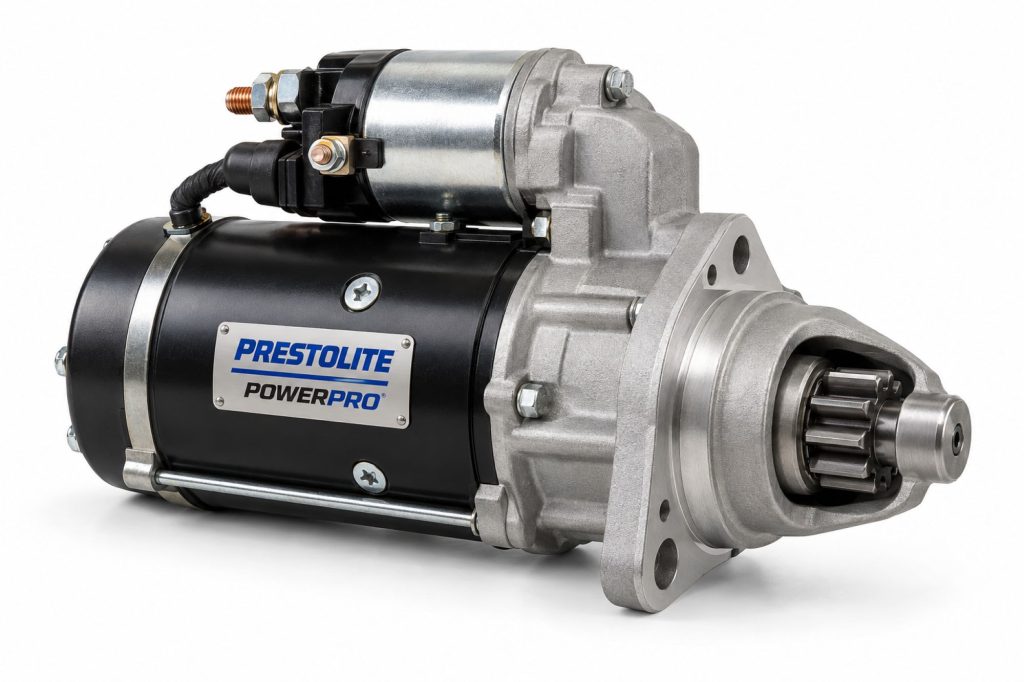
The Prestolite PowerPro is a family of high-torque starters developed for commercial vehicles, vocational equipment, buses, agricultural machinery, construction equipment, and other demanding engine applications.
PowerPro starters generally use gear reduction to multiply the electric motor’s torque before it reaches the engine flywheel. This design can provide powerful cranking performance while allowing the starter to remain smaller and lighter than many comparable direct-drive units.
The PowerPro name covers multiple starter sizes, voltage systems, power ratings, mounting configurations, pinion arrangements, rotations, and engine applications. The complete Prestolite or Leece-Neville part number must be used when identifying a replacement.
Key Characteristics
- Heavy-duty starter family
- High-torque gear-reduction design
- Application-specific 12-volt and 24-volt configurations
- Compact packaging relative to starting output
- Designed for demanding diesel-engine applications
- Solenoid-operated pinion engagement
- Application-specific starter-control technology
- Multiple mounting and flange configurations
- Different power and torque ratings
- Designed to support reliable cold and hot starting
- Available for on-highway and off-highway equipment
- Engine-specific pinion and ring-gear compatibility
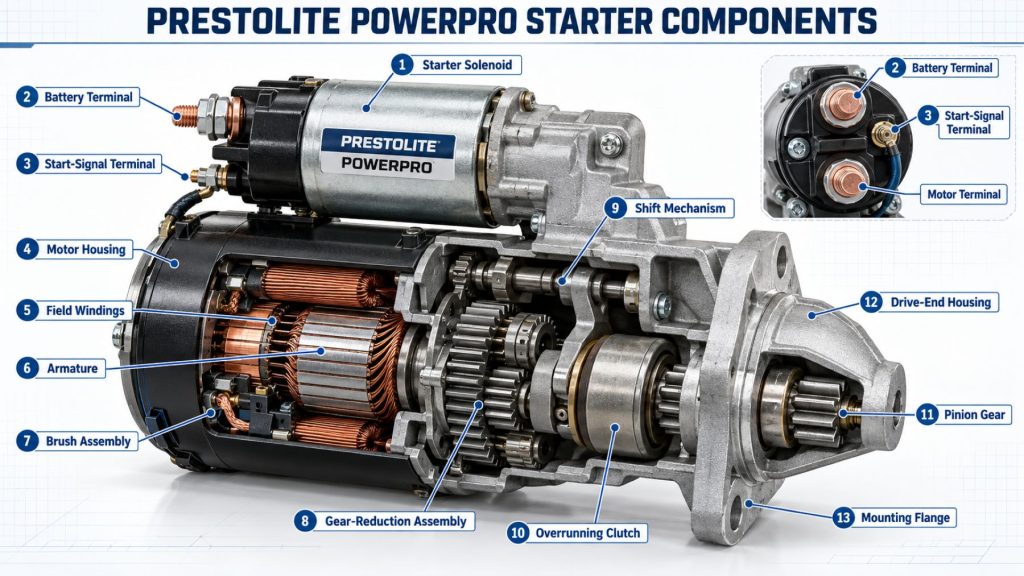
Major Components
- Starter housing
- Electric motor
- Armature
- Field assembly
- Brush holder and brushes
- Commutator
- Starter solenoid
- Magnetic switch or control relay where equipped
- Shift lever
- Pinion gear
- Overrunning clutch
- Planetary gear-reduction assembly
- Drive shaft
- Nose housing or noseless mounting flange
- Electrical terminals
- Bushings or bearings
- Seals and contamination barriers
Product Type and Construction
The PowerPro is an electric starting motor designed to crank an internal-combustion engine until combustion becomes self-sustaining. It combines a high-current electric motor, engagement solenoid, drive assembly, overrunning clutch, and reduction gears in one engine-mounted unit.
Application-specific construction may include corrosion-resistant housing protection, heavy-duty brushes, an enlarged armature, high-capacity terminals, sealed control components, and a compact in-line gear-reduction arrangement.
How the Electrical Component or System Works
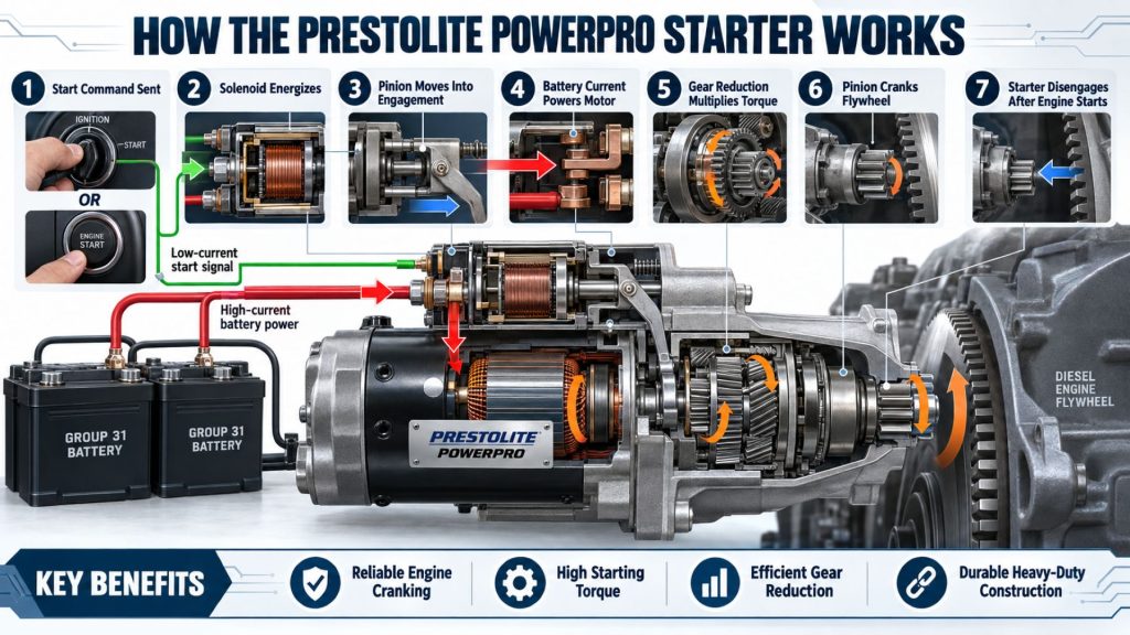
When the operator activates the start command, a control circuit energizes the starter solenoid. The solenoid moves the starter pinion into engagement with the engine flywheel or flexplate ring gear and closes the high-current contacts supplying battery power to the starter motor.
The electric motor rotates the reduction-gear assembly, which multiplies torque and turns the pinion. The pinion rotates the engine crankshaft until the engine starts. When the start command is released, the solenoid opens the electrical circuit and retracts the pinion.
Position and Function Within the Vehicle
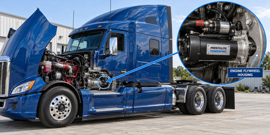
The starter is mounted to the engine flywheel housing or bell housing. Its pinion is positioned next to the ring gear so it can engage the engine only during a starting attempt.
The starter’s function is limited to cranking the engine. Once the engine starts, the overrunning clutch and retraction mechanism protect the starter from being driven continuously by the faster-moving flywheel.
Common Specifications
- Product Type: Heavy-duty electric starter
- Drive Design: Application-specific gear reduction
- System Voltage: Model-specific 12 or 24 volts
- Power Output: Part-number- and engine-specific
- Rotation: Application-specific
- Pinion Gear: Engine-specific tooth count, pitch, diameter, and position
- Mounting: Application-specific flange, bolt pattern, and register diameter
- Engagement: Solenoid-operated shift mechanism
- Grounding: Insulated-return or case-ground configuration, depending on model
- Control Terminals: Application-specific solenoid and relay connections
- Primary Engine Type: Commercial diesel and other approved heavy-duty engines
Operating Capacity and Performance
Starter performance is determined by system voltage, available battery current, starter power, gear reduction, engine displacement, engine compression, temperature, lubricant viscosity, cable resistance, and flywheel condition.
The correct PowerPro model should provide enough cranking torque and speed for the approved engine without exceeding the starter’s duty-cycle limits. Published performance data must be checked for the individual part number.
Installation Position and System Function
The starter’s mounting position is determined by the engine flywheel housing. Proper positioning establishes the required pinion-to-ring-gear alignment, engagement depth, and clearance.
The starter connects the vehicle’s stored battery energy to the engine mechanically for only a short cranking period. It is not designed for continuous operation.
System Voltage and Electrical Architecture
The starter must match the vehicle’s nominal electrical system and battery arrangement. A 12-volt starter cannot be substituted for a 24-volt starter, or the reverse, without an engineered conversion of the starting system.
The starting architecture may also include battery disconnects, series-parallel switches, starter relays, electronic start controls, neutral-safety circuits, engine controllers, and low-voltage protection.
Electrical Input, Output, and Power Function
The starter receives high-current direct-current power from the batteries. Its output is mechanical torque delivered through the pinion to the flywheel ring gear.
Current demand is highest when the engine first begins to turn. Low temperature, thick lubricant, high engine compression, weak batteries, and excessive circuit resistance can increase the electrical demand or reduce cranking speed.
Voltage, Current, and Electrical Load Management
Available voltage at the starter must remain high enough during cranking for the motor and control circuits to operate correctly. Excessive voltage drop in positive cables, ground cables, disconnect switches, relays, or terminals can cause slow cranking or solenoid chatter.
Cranking current should be evaluated with battery condition, ambient temperature, and engine resistance in mind. High current does not automatically prove that the starter has failed.
Starting and Engine-Cranking Function
The PowerPro starter must rotate the crankshaft fast enough for the engine’s fuel, air, compression, and electronic-control systems to begin normal operation. Required cranking speed varies by engine design and temperature.
A slow-cranking complaint can originate from the starter, batteries, wiring, engine oil, internal engine condition, flywheel, fuel system, or electronic controls.
Gear-Reduction and Torque Delivery
The gear-reduction assembly allows the electric motor to rotate faster than the starter pinion. The reduction gears convert that speed into increased pinion torque, helping the starter crank large diesel engines from a relatively compact package.
The reduction ratio, motor characteristics, and pinion design are selected for the intended engine. These specifications should not be altered during replacement.
Pinion, Ring Gear, and Engagement Design
The pinion gear must match the engine ring gear in tooth count, pitch, diameter, rotation, and engagement position. The solenoid and shift mechanism move the pinion into place before full cranking torque is applied.
Incorrect specifications can cause incomplete engagement, tooth damage, grinding, pinion milling, starter kickback, or failure to crank.
Internal Components and Electrical Design
The starter motor contains an armature, field system, commutator, brushes, bearings or bushings, and high-current electrical connections. The solenoid uses an electromagnetic coil to move the drive and close the main contacts.
Application-specific PowerPro models may include an Integral Magnetic Switch or other relay arrangement intended to reduce control-circuit voltage loss and improve solenoid operation.
Materials and Component Construction
Construction may include cast-metal housings, copper windings and conductors, a steel armature shaft, hardened reduction gears, heavy-duty brushes, sealed bearings or bushings, insulated terminals, and corrosion-resistant exterior coatings.
Materials and protective treatments vary according to starter size, operating environment, and engine application.
Wiring, Terminals, Connectors, and Grounding
The main battery and ground cables must carry substantial current with minimal resistance. Terminal surfaces should be clean, properly supported, correctly insulated, and tightened to the specified torque.
The solenoid control terminal must receive adequate voltage during cranking. Insulated-return starters require a dedicated ground connection and should not rely solely on the starter housing for the return path.
Circuit Protection and Electrical Safety
Starter circuits carry extremely high current. Cables must be routed and protected against abrasion, exhaust heat, rotating parts, sharp edges, and accidental short circuits.
Battery disconnects, starter relays, control circuits, and protective devices must meet the vehicle manufacturer’s requirements. Improper components can create voltage loss, overheating, fire risk, or unintended starter engagement.
Controls, Monitoring, and Diagnostics
The starter may be controlled through an ignition switch, push-button circuit, body controller, engine controller, neutral-safety system, starter relay, or electronic protection module. Some vehicles record starting-system voltage and fault information.
Diagnosis should include battery testing, cable voltage-drop measurements, control-circuit testing, current draw, cranking speed, ring-gear inspection, and confirmation that the engine can rotate normally.
Electronic Controls and Driver-Assistance Integration
Modern vehicles may use electronic controls to authorize starting only when transmission position, immobilizer status, engine conditions, battery voltage, and safety interlocks are correct.
The starter does not operate driver-assistance equipment directly, but inadequate cranking voltage can interrupt communication among engine, transmission, brake, steering, safety, and body-control modules.
Power Demand, Capacity, and Energy Management
Starter selection must account for engine displacement, compression, minimum cranking speed, ambient temperature, battery capacity, cable length, system voltage, and expected starting frequency.
The batteries must supply the required current without excessive voltage collapse. Repeated starting attempts can quickly discharge batteries and overheat the starter.
Power Consumption and System Efficiency
Gear reduction allows a smaller electric motor to produce substantial pinion torque efficiently. Actual starting efficiency depends on battery condition, cable resistance, mechanical alignment, temperature, engine resistance, and starter condition.
Loose or corroded connections convert battery energy into unwanted heat and reduce the power available for cranking.
Heat, Efficiency, and Electrical Loss Management
High current generates heat in the motor windings, solenoid contacts, brushes, commutator, cables, and terminals. Starter duty-cycle limits allow these components time to cool between attempts.
Extended cranking, low voltage, mechanical binding, repeated engagement, or high-resistance connections can increase heat and shorten starter life.
Environmental Sealing and Contamination Protection
PowerPro starters may operate around water, dust, mud, salt, oil, fuel, and road debris. Application-specific housings, seals, coatings, and terminal protection help resist contamination and corrosion.
No starter should be treated as immune to direct pressure washing, prolonged submersion, damaged seals, leaking fluids, or unprotected electrical connections.
Duty Cycle and Operating Conditions
The PowerPro is designed for short-duration engine-cranking cycles rather than continuous operation. Maximum cranking time and required cooling intervals depend on the starter, engine, temperature, and manufacturer instructions.
Severe cold, high underhood temperature, frequent stop-start operation, contaminated environments, and difficult engine starting can increase starter stress.
Mounting and Installation
The starter must match the original mounting flange, bolt pattern, register, pinion position, rotation, and clearance. Mounting surfaces should be clean and free from damage before installation.
Fasteners must be installed and tightened according to the engine or starter manufacturer’s specifications. Loose mounting can cause misalignment, noise, broken housings, and ring-gear damage.
Wiring, Grounding, and Installation Requirements
Battery, ground, and control cables must be connected to the correct terminals. Cable size must account for system voltage, starter current, circuit length, conductor material, temperature, and allowable voltage drop.
Insulating boots, cable supports, heat shields, and routing clips should be restored during installation. Cables must not place excessive force on the starter terminals.
Vehicle and Electrical-System Compatibility
Compatibility depends on system voltage, engine model, flywheel housing, pinion specifications, mounting, rotation, starter power, grounding method, control circuit, battery capacity, cable size, and physical clearance.
A starter should not be selected solely because its mounting holes appear to align. Internal gearing, pinion position, rotation, and electrical requirements must also match.
Battery and Starting-System Compatibility
The vehicle’s batteries must provide the required voltage and cold-cranking capacity. Batteries connected in a bank should be compatible in type, capacity, age, condition, and state of charge.
Battery switches, series-parallel controls, cables, grounds, and relays must support the starter without creating excessive resistance or voltage loss.
Related Component and System Compatibility
- Engine flywheel and ring gear
- Flywheel or bell housing
- Vehicle batteries
- Battery cables and grounds
- Battery disconnect switches
- Starter relays and magnetic switches
- Ignition or start controls
- Engine control module
- Transmission neutral-safety circuit
- Engine-block and chassis grounding system
- Cold-start assistance equipment
- Charging system
Common Applications
- Heavy-duty highway tractors
- Vocational trucks
- Transit buses
- School buses
- Motor coaches
- Emergency vehicles
- Concrete mixers
- Construction equipment
- Mining equipment
- Agricultural machinery
- Refuse trucks
- Utility vehicles
- Industrial engines
- Generator sets
Advantages
- High cranking torque
- Compact gear-reduction construction
- Reduced weight compared with some direct-drive designs
- Application-specific heavy-duty construction
- Suitable for demanding diesel engines
- Multiple voltage and power configurations
- Can support reliable starting in severe conditions
- Available for numerous on-highway and off-highway applications
- Application-specific corrosion and contamination protection
- Designed to reduce downtime when properly matched and maintained
Limitations or Considerations
- Specifications differ among PowerPro part numbers
- Starter voltage must match the vehicle
- Pinion and ring-gear specifications must match exactly
- Mounting configurations are not universally interchangeable
- Starter performance depends heavily on battery condition
- High-resistance cables can cause starting problems
- Extended cranking can overheat the starter
- Engine mechanical problems can imitate starter failure
- Improper installation can damage the ring gear
- Control-relay requirements vary by application
- A larger starter will not correct weak batteries or damaged wiring
Driver and Operator Experience
A correctly matched PowerPro starter should provide prompt and consistent engine cranking. The operator may notice faster engagement and stronger cranking compared with a worn or undersized starter.
Slow cranking, repeated clicking, grinding, delayed engagement, smoke, unusual odors, or a starter that remains engaged after the engine starts should be reported immediately.
Controls, Indicators, and Driver Feedback
The driver normally controls the starter through an ignition switch or push-button start command. Vehicle electronics may provide low-voltage warnings, start-inhibit messages, neutral-position warnings, or diagnostic fault information.
The operator should release the start control as soon as the engine begins running and allow the required cooling interval after an unsuccessful attempt.
Common Electrical Tests and Diagnostic Information
- Battery state-of-charge test
- Battery conductance or load test
- Open-circuit battery-voltage measurement
- Cranking-voltage test
- Starter current-draw test
- Positive-circuit voltage-drop test
- Ground-circuit voltage-drop test
- Solenoid control-voltage test
- Starter-relay test
- Engine cranking-speed measurement
- Flywheel ring-gear inspection
- Starter pinion inspection
- Engine mechanical-rotation check
Inspection and Wear Points
- Battery terminals
- Positive starter cable
- Ground cables and bonding straps
- Solenoid control wire
- Starter relay
- Main starter terminals
- Mounting bolts
- Mounting flange
- Starter housing
- Pinion gear
- Flywheel ring gear
- Solenoid contacts
- Brushes and commutator
- Bearings and bushings
- Seals and protective boots
Cooling, Ventilation, and Environmental Requirements
The starter cools between short operating cycles. It should not be exposed to cranking periods longer than those permitted by the starter and engine manufacturers.
Heat shields, protective covers, cable boots, and environmental seals should remain in place. Oil, coolant, fuel, hydraulic fluid, or exhaust heat can damage the starter and its electrical connections.
Component Service Life and Rebuildability
Starter life depends on starting frequency, crank duration, battery condition, circuit resistance, engine condition, mounting alignment, temperature, vibration, and contamination.
Some PowerPro starters may be professionally rebuilt using approved components. Other applications may favor a new or manufacturer-supported remanufactured replacement. Any rebuild must preserve the original electrical and mechanical specifications.
Maintenance and Ownership Notes
Routine starting-system maintenance should include battery testing, cleaning and tightening connections, inspecting cables and grounds, checking mounting fasteners, and investigating changes in cranking speed or engagement noise.
A complete system diagnosis should be performed before replacing the starter. Many apparent starter failures are caused by weak batteries, excessive voltage drop, control-circuit faults, damaged ring-gear teeth, or engine mechanical problems.
Common Electrical-System Problems
- Starter does not operate: Discharged batteries, open circuits, a faulty relay, damaged solenoid, start-inhibit condition, poor grounding, or internal starter failure may be responsible.
- Slow cranking: Weak batteries, high cable resistance, incorrect starter selection, worn internal components, cold oil, or engine mechanical resistance can reduce speed.
- Solenoid clicks repeatedly: Low voltage, loose battery connections, damaged cables, weak batteries, or poor control-circuit power can cause chatter.
- Starter spins without cranking the engine: A damaged pinion, failed overrunning clutch, engagement problem, or damaged ring gear may prevent torque transfer.
- Grinding during engagement: Incorrect pinion specifications, damaged ring-gear teeth, loose mounting, misalignment, or solenoid problems may be responsible.
- Starter remains engaged: A sticking solenoid, welded contacts, faulty start switch, relay problem, control-module fault, or damaged drive can prevent disengagement.
- Overheated cables or terminals: Loose connections, corrosion, undersized cables, damaged lugs, or excessive current can generate heat.
- Repeated starter failure: Long cranking periods, weak batteries, engine-starting problems, flywheel damage, wiring resistance, contamination, or an incorrect replacement may shorten service life.
Safety and Service Precautions
Disconnect and isolate the batteries according to the vehicle manufacturer’s procedure before removing starter cables or mounting hardware. Starter circuits can produce severe arcing, burns, fire, component damage, or unintended engine cranking.
Secure the vehicle, place the transmission in the required position, and prevent unintended movement. Support the starter during removal because heavy-duty units may be difficult to control in confined spaces.
Identification Information
Identification information is normally found on the starter label, housing, or manufacturer plate. Record the complete part number before ordering a replacement.
- Manufacturer and brand
- Complete starter part number
- Serial or production code
- Nominal voltage
- Power rating
- Rotation
- Pinion tooth count
- Pinion pitch and diameter
- Mounting flange and bolt pattern
- Register diameter
- Grounding configuration
- Solenoid and relay arrangement
- Engine manufacturer and model
- Vehicle identification number
Buying Considerations
- Confirm the complete original starter part number
- Match the vehicle’s nominal voltage
- Verify starter power and torque requirements
- Match the engine and flywheel housing
- Confirm the mounting flange and bolt pattern
- Verify rotation
- Match pinion tooth count, pitch, diameter, and position
- Confirm case-ground or insulated-return construction
- Match solenoid and relay connections
- Check clearance around the engine and exhaust system
- Review contamination and temperature requirements
- Check new and remanufactured replacement options
- Confirm warranty terms for the selected part number
Variants and Configurations
- 12-volt starters
- 24-volt starters
- Different power ratings
- Different gear-reduction ratios
- Different mounting flanges
- Different pinion tooth counts
- Different rotations
- Case-ground configurations
- Insulated-return configurations
- Different solenoid positions
- Integral Magnetic Switch-equipped applications
- On-highway configurations
- Off-highway configurations
- Engine-specific replacement models
Comparison to Similar Equipment
Compared with the Delco Remy 39MT Heavy-Duty Gear-Reduction Starter, the PowerPro provides an alternative family of high-torque starters. Mounting, pinion, electrical connections, controls, and approved engine applications must be compared by part number.
Compared with the Delco Remy 38MT Heavy-Duty Starter, the correct choice depends on engine size, required cranking power, system voltage, mounting dimensions, and original equipment specifications.
Compared with a direct-drive starter, a gear-reduction PowerPro model can produce substantial cranking torque from a smaller and lighter package. Direct-drive starters may use a simpler mechanical arrangement but can be larger and heavier for comparable applications.
Best Fit For
- Vehicles originally equipped with a compatible PowerPro starter
- Heavy-duty diesel engines
- Vocational trucks operating in demanding environments
- Buses requiring dependable starting performance
- Construction and mining equipment
- Agricultural machinery
- Emergency vehicles
- Applications requiring compact gear-reduction construction
- Vehicles operating in hot or cold conditions
- Fleets seeking an application-specific heavy-duty starter
Related Vehicle and Trailer Types
- Highway tractors
- Vocational trucks
- Transit buses
- School buses
- Motor coaches
- Emergency vehicles
- Concrete mixers
- Refuse trucks
- Utility trucks
- Construction equipment
- Mining equipment
- Agricultural machinery
Related Truck and Trailer Models
- Freightliner Cascadia
- Freightliner 114SD
- Kenworth T680
- Kenworth T880
- Peterbilt 579
- Peterbilt 567
- International LT Series
- International HX Series
- Volvo VNL
- Volvo VHD
- Mack Anthem
- Mack Granite
Related Electrical System Types
- Starters & Starting Systems
- Commercial Truck Batteries & Energy Storage
- Alternators & Charging Systems
- Wiring, Connectors & Power Distribution
- Inverters, Converters & Auxiliary Electrical Power
Related Electrical Products
- Delco Remy 39MT Heavy-Duty Gear-Reduction Starter
- Delco Remy 38MT Heavy-Duty Starter
- Leece-Neville IdlePro Alternator
- Leece-Neville IdlePro Extreme Alternator
- Delco Remy 40SI Heavy-Duty Brushless Alternator
- Delco Remy 36SI High-Output Alternator
- Delco Remy 28SI High-Output Alternator
- Delco Remy 24SI Heavy-Duty Alternator
- Deka Intimidator AGM Group 31 Battery
Related Equipment Systems
- Electrical Systems
- Engines
- Transmissions
- Drivelines & Steering Systems
- PTO & Hydraulic Systems
- Safety Systems
- Telematics & ELD Systems
Related Guides
- Electrical System Guides
- How Commercial Truck Electrical Systems Work
- Commercial Truck Starters and Starting Systems Explained
- Commercial Truck Batteries Explained
- Commercial Truck Alternators and Charging Systems Explained
- How to Inspect and Maintain Truck Wiring and Electrical Connections
Regulatory and Compliance Notes
Starter replacement or starting-system modification must preserve compliance with applicable vehicle electrical, emissions, safety, and electromagnetic-compatibility requirements. Critical safety interlocks and start-inhibit controls must remain functional.
The starter’s power rating does not change the engine’s approved starting procedure. Installation should follow the engine, vehicle, and starter manufacturers’ instructions.
Real World Operating Notes
A starter that turns slowly is not automatically defective. Battery state of charge and voltage drop across the complete high-current circuit should be checked before the starter is removed.
Repeated cranking can overheat a new starter just as quickly as an older unit. Fuel, air, compression, cold-start, and electronic-control problems should be corrected instead of relying on prolonged cranking.
Ring-gear condition should be inspected when a starter has damaged pinion teeth or repeatedly produces grinding noises. Installing another starter without correcting ring-gear damage can cause another failure.
Frequently Asked Questions
What is the Prestolite PowerPro Starter?
It is a family of high-torque, heavy-duty starters designed for commercial vehicles, buses, agricultural machinery, construction equipment, mining equipment, and other demanding engine applications.
Does the PowerPro use gear reduction?
PowerPro products include application-specific gear-reduction starters. The exact internal design should be confirmed using the complete part number.
Is the PowerPro available in 12-volt and 24-volt versions?
The broader PowerPro family includes different electrical configurations. The starter voltage must match the vehicle and battery system.
Can any PowerPro starter fit any diesel engine?
No. Mounting, rotation, pinion, voltage, power, grounding, terminals, control circuits, and flywheel compatibility are application-specific.
What causes a starter to crank slowly?
Possible causes include weak batteries, excessive cable resistance, poor grounds, internal starter wear, cold lubricant, incorrect starter selection, or mechanical resistance inside the engine.
Why does the starter click without turning the engine?
Low voltage, loose connections, damaged cables, weak batteries, faulty solenoid contacts, a defective relay, or a mechanically locked engine may be responsible.
What causes grinding during starting?
Damaged pinion or ring-gear teeth, incorrect pinion specifications, loose mounting, poor alignment, or incomplete solenoid engagement can cause grinding.
Can the starter be tested without checking the batteries?
A complete diagnosis should include the batteries, cables, grounds, controls, current draw, cranking speed, and starter. Testing only the starter may miss the actual cause.
Can a higher-power starter replace the original unit?
Only when the replacement is approved for the engine and matches all electrical, mounting, pinion, rotation, clearance, and control requirements.
How is the correct PowerPro replacement identified?
Use the original part number, vehicle identification number, engine model, system voltage, mounting configuration, pinion specifications, rotation, and terminal arrangement.
Availability and Where to Find
Prestolite PowerPro starters may be available through Prestolite Electric distributors, heavy-duty electrical specialists, commercial-truck dealers, engine dealers, fleet-parts suppliers, equipment dealers, and authorized rebuilders.
Availability depends on voltage, power rating, engine application, mounting, pinion, rotation, grounding, and control configuration. Buyers should verify the complete part number and current supersession information before ordering.
Current product information, application assistance, distributor resources, and technical support are available through the Prestolite Electric website.
Support Trucking Families
Truck Equipment Atlas supports the mission of Grey Cross, a nonprofit dedicated to helping families of truck drivers who lose their lives while on the road. As the site grows, part of its mission is to bring awareness and support to these families.
Podcast or Video Section
Learn More Through Audio and Video
Truck Equipment Atlas will continue expanding with podcast episodes, interviews, and equipment breakdowns to help drivers and fleets better understand trucks and equipment.
Follow the Growth of Truck Equipment Atlas
Truck Equipment Atlas continues to expand with new truck profiles, trailer coverage, diesel engine pages, equipment system resources, manufacturer information, and educational guides.
Visit our Site Updates page to explore recent additions, project milestones, and upcoming resources as we continue building one of the industry’s growing commercial trucking equipment reference libraries.
View the Latest Site Updates: Truck Equipment Atlas Site Updates