
Bendix Tu-Flo 550 Air Compressor
Quick Facts
- Manufacturer: Bendix Commercial Vehicle Systems
- Product Series: Tu-Flo
- Model: Tu-Flo 550
- Product Type: Engine-driven reciprocating air compressor
- Brake-System Category: Air supply and air management
- Compressor Design: Two-cylinder, single-stage reciprocating compressor
- Cooling: Engine coolant
- Lubrication: Engine lubrication system
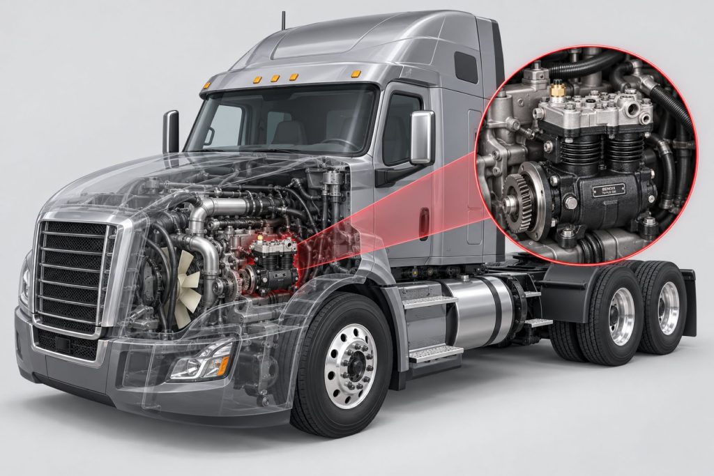
- Typical Mounting: Engine-mounted and gear-driven
- Primary Function: Produces compressed air for the vehicle’s air-brake system and approved pneumatic accessories
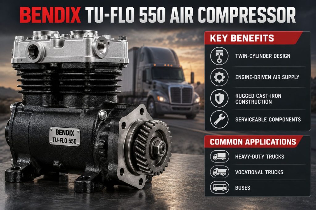
- Common Applications: Medium-duty and heavy-duty trucks, tractors, buses, and specialty commercial vehicles
- Production Status: Commonly encountered as original equipment, service replacement, or remanufactured equipment; exact availability depends on part number and application
- Primary Benefit: Proven compressed-air production for commercial-vehicle braking systems
Overview
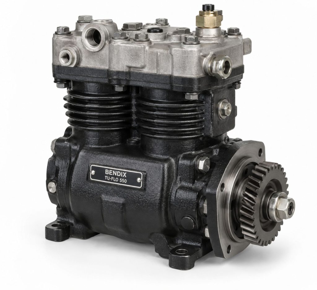
The Bendix Tu-Flo 550 is an engine-driven air compressor used to supply compressed air for commercial-vehicle air-brake systems. It is part of the established Bendix Tu-Flo compressor family and has been installed across numerous medium-duty and heavy-duty trucks, tractors, buses, and specialty vehicles.
The compressor draws filtered air into its cylinders, compresses it, and sends the pressurized air through the discharge line to the vehicle’s air dryer and reservoir system. Stored air is then available for service brakes, spring-brake release, and approved pneumatic accessories.
The Tu-Flo 550 is a two-cylinder, single-stage reciprocating compressor. It commonly receives lubrication and coolant from the engine and is mechanically driven by the engine’s gear train.
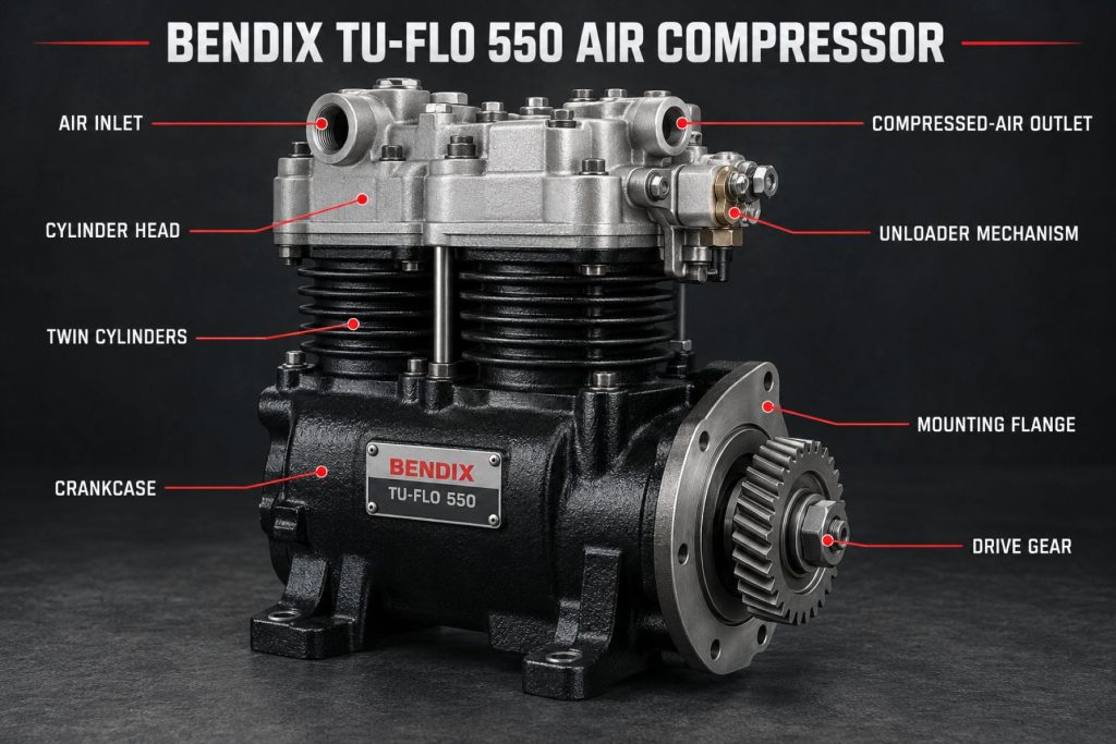
Numerous application-specific Tu-Flo 550 configurations have been produced. Mounting flange, drive gear, cylinder-head orientation, air inlet, discharge port, coolant ports, oil connections, governor controls, and identification numbers must be verified before ordering a replacement.
Key Characteristics
- Two-cylinder reciprocating compressor
- Single-stage air compression
- Engine-driven operation
- Engine-supplied lubrication
- Engine-coolant circulation
- Designed for commercial air-brake systems
- Supplies compressed air to the air dryer and reservoirs
- Works with an air-compressor governor
- Loaded and unloaded operating modes
- Available in application-specific configurations
- Established heavy-duty service history
- Original, service-remanufactured, and replacement options may be available
- Compatible with multiple medium-duty and heavy-duty vehicle applications when correctly specified
Major Components
- Compressor crankcase
- Cylinder block
- Cylinder head
- Compressor pistons
- Piston rings
- Connecting rods
- Crankshaft
- Crankshaft bearings
- Inlet valves
- Discharge valves
- Unloader pistons
- Unloader mechanism
- Air inlet
- Discharge port
- Coolant inlet and outlet ports
- Lubricating-oil passages
- Drive gear or coupling
- Mounting flange
- Rear cover
- Governor-control connection
- Gaskets and seals
- Safety and pressure-control components within the complete air system
How the Brake Component or System Works
The vehicle’s engine mechanically drives the compressor crankshaft. As the crankshaft rotates, connecting rods move the compressor pistons up and down inside the cylinders.
During the intake stroke, a piston moves downward and creates low pressure inside the cylinder. The inlet valve opens, allowing filtered air to enter.
During the compression stroke, the piston moves upward. The inlet valve closes, and the trapped air is compressed.
When cylinder pressure becomes high enough, the discharge valve opens. Compressed air leaves the cylinder head through the discharge port and enters the compressor discharge line.
The discharge line carries the hot compressed air toward the air dryer. The dryer removes moisture, oil aerosols, and contamination before the air enters the vehicle reservoirs.
The compressor does not operate at full delivery continuously. A governor monitors system pressure and controls the compressor’s loading and unloading cycle.
When reservoir pressure falls to the governor’s cut-in setting, the compressor returns to its loaded or pumping mode. When pressure reaches the cut-out setting, the governor sends control air to the compressor’s unloader mechanism.
The unloaders hold the inlet valves open so the compressor stops delivering compressed air to the reservoirs even though its internal components continue moving with the engine.
Position and Function Within the Brake System
The Tu-Flo 550 is part of the air-supply section of a commercial air-brake system.
The normal air-flow sequence is:
- Engine-driven compressor
- Compressor discharge line
- Air dryer
- Supply or wet reservoir
- Primary and secondary reservoirs
- Air-brake control valves
- Brake chambers and actuators
- Foundation brakes
The compressor creates the air supply used throughout the system. It does not directly apply the wheel brakes.
Compressed air produced by the Tu-Flo 550 may support:
- Service-brake applications
- Spring-brake release
- Parking-brake control
- Trailer air supply
- Air suspension
- Transmission controls
- Air-operated accessories
- Horn systems
- Seat controls
- Other approved pneumatic equipment
Accessory demand must be considered when determining whether the compressor and air system are appropriate for a vehicle.
Common Specifications
- Compressor Type: Two-cylinder reciprocating air compressor
- Compression Stages: Single stage
- Nominal Displacement: Application and operating-speed dependent; commonly associated with approximately 13 cubic feet per minute in published Tu-Flo 550 service information
- Drive Type: Engine-driven
- Lubrication: Pressure lubrication supplied by the engine
- Cooling: Engine coolant
- Air Inlet: Naturally aspirated or connected to the engine air-intake system, depending on application
- Pressure Control: External governor operating the compressor unloader system
- Discharge Connection: Application-specific
- Mounting Arrangement: Application-specific flange and engine installation
- Drive Gear: Engine- and application-specific
- Rotation: Determined by the approved engine installation
- Operating Speed: Determined by engine gearing and application
- Replacement Type: New, service replacement, or remanufactured, depending on part number and availability
Exact specifications must be confirmed using the complete Bendix part number, vehicle identification number, engine information, and compressor identification markings.
Operating Specifications and Performance
The Tu-Flo 550’s air-delivery performance depends on compressor speed, inlet restriction, discharge pressure, engine condition, temperature, duty cycle, and the condition of the compressor.
A properly operating compressor must build and maintain enough air pressure to support the vehicle’s braking system and approved pneumatic accessories.
Performance can be affected by:
- Compressor rotational speed
- Engine idle speed
- Drive ratio
- Governor cut-in and cut-out settings
- Air-inlet restriction
- Discharge-line restriction
- Air-dryer condition
- Reservoir capacity
- Air-system leakage
- Accessory air consumption
- Compressor wear
- Piston-ring condition
- Valve condition
- Cooling-system performance
- Lubrication quality
- Ambient temperature
- Vehicle duty cycle
A compressor should be evaluated as part of the complete charging system. Slow pressure buildup does not automatically prove that the compressor has failed.
Braking Performance and System Integration
The Tu-Flo 550 does not create friction at the wheels, but its performance directly affects the air pressure available to the braking system.
Insufficient air production may cause:
- Slow pressure buildup
- Frequent low-air warnings
- Delayed spring-brake release
- Reduced air reserve
- Frequent compressor operation
- Difficulty supporting trailer air demand
- Inability to operate approved pneumatic accessories normally
- Extended recovery time after repeated brake applications
A properly maintained compressor supports reliable operation of:
- Primary service-brake circuit
- Secondary service-brake circuit
- Spring brakes
- Trailer brakes
- Antilock braking systems
- Electronic stability-control systems
- Air disc brakes
- Drum brakes
- Air-operated auxiliary systems
Brake performance still depends on reservoirs, valves, chambers, foundation brakes, tires, vehicle loading, and driver operation.
Air Supply, Controls, and Electronic Integration
The Tu-Flo 550 works with a mechanical or air-controlled governor that monitors reservoir pressure.
The governor normally provides two basic operating commands:
Cut-in command when pressure falls
Cut-out command when pressure reaches the upper operating range
During cut-in, the compressor is loaded and supplies air.
During cut-out, governor pressure operates the unloader mechanism and stops normal air delivery.
The compressor may be integrated with:
- Air dryer
- Air-dryer purge reservoir
- Supply reservoir
- Primary reservoir
- Secondary reservoir
- Pressure-protection valves
- Low-air warning devices
- Pressure gauges
- Electronic pressure sensors
- Engine electronic controls
- Vehicle diagnostic systems
- Air-system monitoring equipment
The Tu-Flo 550 itself is primarily mechanical and pneumatic, but the complete vehicle may use electronic sensors and controllers to monitor air pressure, compressor operation, or system faults.
Installation, Adjustment, and Brake Balance
Correct compressor installation is necessary for reliable air-system operation.
Important installation considerations include:
- Correct compressor part number
- Approved engine application
- Mounting-flange compatibility
- Drive-gear compatibility
- Gear backlash
- Correct rotation
- Proper mounting-fastener torque
- Oil-supply connection
- Oil-drain alignment
- Coolant-line routing
- Air-inlet routing
- Discharge-line routing
- Governor-control connection
- Clearance from exhaust components
- Clearance from moving engine components
- Correct gasket and seal installation
- Freedom from air, coolant, and oil leaks
The compressor does not directly determine left-to-right or axle-to-axle brake balance. However, inadequate system pressure can affect the operation of every brake circuit.
Compressor replacement should be followed by confirmation of normal pressure buildup, governor operation, air-dryer purging, system leakage, low-air warnings, and brake operation.
Foundation Brake, Axle, and Wheel-End Compatibility
The Tu-Flo 550 can support commercial vehicles equipped with different foundation-brake and axle configurations when the complete air system is properly designed.
Possible applications include:
- S-cam drum brakes
- Air disc brakes
- Single rear axles
- Tandem drive axles
- Multiple drive axles
- Steer-axle brakes
- Lift axles
- Pusher axles
- Tag axles
- Trailer air brakes
- Bus brake systems
- Specialty-vehicle brake systems
The compressor is not selected solely according to whether the vehicle uses drum or air disc brakes.
Compatibility also depends on:
- Number of axles
- Number and size of brake chambers
- Trailer operation
- Reservoir capacity
- Accessory air demand
- Vehicle duty cycle
- Engine configuration
- Compressor drive ratio
- Required air-system recovery rate
- Applicable vehicle requirements
Common Applications
- Class 6 commercial trucks
- Class 7 commercial trucks
- Class 8 highway tractors
- Regional-haul tractors
- Vocational trucks
- Dump trucks
- Concrete mixers
- Refuse trucks
- Utility trucks
- Municipal vehicles
- Buses
- School buses
- Transit buses
- Fire apparatus
- Emergency vehicles
- Recovery vehicles
- Construction trucks
- Specialty commercial vehicles
The Tu-Flo 550 has been produced in numerous configurations, so installation on a vehicle family does not confirm that every model or production year uses the same compressor.
Vehicle and Brake-System Compatibility
The correct Tu-Flo 550 configuration must match the vehicle’s engine and complete air system.
Compatibility depends on:
- Vehicle manufacturer
- Vehicle model
- Model year
- Vehicle identification number
- Engine manufacturer
- Engine model
- Engine serial number
- Compressor mounting flange
- Drive gear
- Gear position
- Compressor rotation
- Cylinder-head orientation
- Air-inlet arrangement
- Discharge-port location
- Governor configuration
- Oil-supply arrangement
- Oil-drain arrangement
- Coolant-port location
- Air-dryer configuration
- Reservoir capacity
- Brake-system demand
- Accessory air demand
A compressor should not be ordered only by the Tu-Flo 550 family name. Two Tu-Flo 550 compressors can look similar but use different mounting, gearing, ports, heads, or internal configurations.
Advantages
- Established commercial-vehicle compressor design
- Two-cylinder air delivery
- Engine-driven operation
- Engine-supplied lubrication
- Engine-coolant circulation
- Supports medium-duty and heavy-duty air-brake systems
- Works with Bendix air dryers and governors when properly specified
- Broad historical application base
- Service knowledge is widely available
- New or remanufactured replacements may be available
- Rebuild and service components may be available for specific configurations
- Can support truck, tractor, bus, and specialty-vehicle applications
- Provides air for braking and approved pneumatic accessories
Limitations or Considerations
- Application-specific mounting and gearing
- Multiple Tu-Flo 550 configurations exist
- Part numbers may not be interchangeable
- Requires proper engine lubrication
- Requires proper coolant flow
- Discharge air becomes extremely hot
- Oil carryover can contaminate the air system
- Carbon can accumulate in the discharge line
- Air leaks can cause excessive compressor duty cycle
- High accessory demand can shorten compressor life
- Improper governor operation can affect loading and unloading
- Cooling-system problems can cause overheating
- Some configurations may be older or superseded
- Remanufactured units must match the original application
- Compressor replacement does not correct leaks or restrictions elsewhere in the air system
Driver and Operator Experience
A correctly operating Tu-Flo 550 should build air pressure within the vehicle manufacturer’s specified time and maintain pressure during normal operation.
Drivers should monitor:
- Primary air-pressure gauge
- Secondary air-pressure gauge
- Low-air warning light
- Low-air warning buzzer
- Air-pressure buildup time
- Governor cut-in
- Governor cut-out
- Frequency of compressor cycling
- Air-dryer purge operation
- Parking-brake release
- Trailer air-supply operation
- Visible or audible air leaks
- Warning messages
A compressor that runs frequently may be responding to an air leak or high pneumatic demand rather than an internal compressor failure.
Drivers should report slow pressure buildup, repeated low-air warnings, abnormal air-dryer purging, excessive compressor cycling, burning odors, coolant loss, oil leakage, or unusual engine-area noises.
Maintenance and Ownership Notes
- Inspect the compressor for oil, coolant, and air leakage.
- Check compressor mounting fasteners.
- Inspect the drive gear and related engine components when accessible.
- Verify engine oil level and condition.
- Maintain the engine lubrication system.
- Maintain the engine cooling system.
- Inspect coolant hoses and fittings.
- Check air-inlet plumbing.
- Inspect the air filter or engine-intake connection.
- Check the compressor discharge line.
- Inspect for carbon buildup or restriction.
- Maintain the air dryer.
- Replace the air-dryer cartridge as required.
- Drain and inspect air reservoirs.
- Monitor reservoir contamination.
- Check governor operation.
- Measure system pressure buildup.
- Perform air-leakage tests.
- Inspect air lines and fittings.
- Monitor compressor duty cycle.
- Investigate excessive oil carryover.
- Follow the approved Bendix and engine-manufacturer service procedures.
- Replacement intervals and maintenance requirements depend on the compressor configuration, vehicle duty cycle, air consumption, engine installation, climate, and operating environment.
Common Brake-System Problems
- Slow pressure buildup: Air-system leaks, a restricted inlet, restricted discharge line, worn compressor components, improper engine speed, governor problems, or air-dryer restrictions may be responsible.
- Compressor will not load: A failed governor, blocked control line, stuck unloader mechanism, incorrect plumbing, or internal damage may prevent normal air delivery.
- Compressor will not unload: Governor failure, a leaking control line, stuck unloader components, or incorrect installation may cause continuous pumping.
- Excessive compressor cycling: Air leaks, high accessory demand, a small reservoir system, governor problems, or incorrect pressure settings may cause frequent loading.
- Excessive oil in the air system: Compressor wear, excessive crankcase pressure, restricted oil return, high duty cycle, inlet restriction, or engine-related problems may contribute to oil carryover.
- Carbon in the discharge line: Excessive heat, restricted flow, long discharge piping, high duty cycle, oil contamination, or inadequate cooling may create deposits.
- Compressor overheating: Low coolant flow, cooling-system restrictions, incorrect installation, high duty cycle, or discharge-line problems may be responsible.
- Coolant leakage: Damaged gaskets, loose fittings, cracked components, or corrosion can allow coolant to escape.
- Oil leakage: Damaged seals, loose fittings, mounting problems, excessive crankcase pressure, or gasket failure may cause leakage.
- Unusual noise: Drive-gear wear, bearing damage, loose mounting, internal wear, or engine gear-train problems may create knocking, grinding, or rattling.
- Air dryer purges too frequently: A system leak, governor problem, high accessory demand, or compressor-control problem may cause repeated purge cycles.
- Pressure exceeds the normal range: Governor malfunction, blocked control plumbing, stuck unloaders, or incorrect system configuration may prevent cut-out.
Safety and Service Precautions
Commercial air-brake systems store compressed air that can cause injury if released unexpectedly.
Before servicing the compressor or connected air system:
- Park the vehicle on a level surface.
- Apply approved parking procedures.
- Block or chock the wheels.
- Drain air pressure from all reservoirs.
- Confirm that stored pressure has been released.
- Allow the engine and compressor to cool.
- Avoid contact with the hot discharge line.
- Disconnect electrical power when required.
- Follow engine shutdown and lockout procedures.
- Use approved lifting and service equipment.
- Wear appropriate personal protective equipment.
- Do not loosen pressurized air, coolant, or oil connections.
- Do not operate the engine with exposed drive gears.
- Do not modify the compressor mounting or drive system.
- Do not reuse damaged fittings, lines, gaskets, or fasteners.
The compressor discharge line can reach extremely high temperatures. Air-system components near the compressor should be allowed to cool before inspection.
After service, the vehicle should be tested for air-pressure buildup, leakage, governor operation, air-dryer purging, warning-system operation, and proper brake performance.
Identification Information
Identification information may be located on a metal tag or stamped area attached to the compressor.
Record the following:
- Compressor manufacturer
- Complete Bendix model designation
- Bendix part number
- Serial number
- Remanufactured part number when applicable
- Vehicle manufacturer
- Vehicle identification number
- Vehicle model and model year
- Engine manufacturer
- Engine model
- Engine serial number
- Compressor mounting style
- Drive-gear information
- Cylinder-head orientation
- Air-inlet location
- Discharge-port location
- Coolant-port arrangement
- Oil-supply connection
- Governor-control arrangement
Do not identify a replacement compressor solely by appearance or the Tu-Flo 550 family name.
Photographs of the tag, mounting flange, drive gear, cylinder head, and port locations can help verify the correct replacement.
Buying Considerations
- Confirm that the original compressor is a Bendix Tu-Flo 550.
- Record the complete Bendix part number.
- Check for superseded part numbers.
- Verify the vehicle identification number.
- Record the engine model and serial number.
- Confirm the mounting-flange design.
- Verify drive-gear compatibility.
- Confirm rotation and drive ratio.
- Match the cylinder-head orientation.
- Verify inlet and discharge connections.
- Confirm oil-supply and oil-drain arrangements.
- Match coolant-port locations.
- Confirm governor compatibility.
- Determine whether a new or remanufactured unit is appropriate.
- Check whether the drive gear is included.
- Check whether fittings, gaskets, and mounting hardware are included.
- Inspect the discharge line and air dryer before installation.
- Correct air-system leaks before replacing the compressor.
- Choose a qualified commercial air-brake or engine technician.
Variants and Configurations
The Tu-Flo 550 designation includes multiple application-specific compressor arrangements.
Differences may include:
- Bendix part number
- New or remanufactured construction
- Mounting flange
- Drive gear
- Gear tooth count
- Gear offset
- Compressor rotation
- Cylinder-head design
- Cylinder-head orientation
- Air-inlet connection
- Discharge-port location
- Coolant-port placement
- Oil-supply connection
- Oil-drain configuration
- Governor-control plumbing
- Rear-cover design
- Engine manufacturer application
- Vehicle manufacturer application
- Accessory drive arrangement
The complete part number and application information should always be used when comparing compressors or ordering replacement components.
Comparison to Similar Equipment
Compared with the Bendix BA-921 Air Compressor, the Tu-Flo 550 is an earlier two-cylinder reciprocating compressor design used across numerous established commercial-vehicle applications. The BA-921 uses a different compressor architecture, mounting arrangement, and application range.
Compared with larger Bendix Tu-Flo compressor models, the Tu-Flo 550 may provide lower nominal air delivery but can be appropriate for vehicles with moderate compressed-air demand.
Compared with smaller compressors, the Tu-Flo 550 can support more demanding air-brake systems, although actual suitability depends on compressor speed, reservoir capacity, accessory demand, and duty cycle.
Compared with an electric air compressor, the Tu-Flo 550 is mechanically driven by the engine and normally shares the engine’s lubrication and cooling systems.
Tu-Flo compressors with different model designations should not be assumed interchangeable. Air delivery, mounting, drive components, cylinder heads, and ports may differ.
Best Fit For
- Vehicles originally equipped with a Bendix Tu-Flo 550
- Medium-duty trucks requiring an engine-driven air compressor
- Heavy-duty trucks and tractors
- Commercial buses
- Vocational vehicles
- Specialty commercial chassis
- Fleets maintaining older Bendix air systems
- Vehicles with compatible engine mounting and drive arrangements
- Operators with access to Bendix technical and service support
- Applications where a correct new or remanufactured replacement is available
- The Tu-Flo 550 is best treated as an application-specific replacement rather than a universal compressor conversion.
Related Vehicle and Trailer Types
- Complete Guide to Semi Truck Types
- Class 6 vs Class 7 vs Class 8 Trucks
- Highway tractors
- Regional tractors
- Day cab trucks
- Sleeper trucks
- Straight trucks
- Dump trucks
- Concrete mixers
- Refuse trucks
- Utility trucks
- Municipal trucks
- Buses
- Fire apparatus
- Emergency vehicles
- Recovery vehicles
- Specialty commercial vehicles
Related Truck and Trailer Models
- Freightliner Cascadia
- Freightliner M2 106
- International LT Series
- International MV Series
- Kenworth T680
- Kenworth T800
- Peterbilt 389
- Peterbilt 579
- Mack Granite
- Volvo VNL
Related Brake System Types
- Air Brake Systems
- Air Disc Brake Systems
- Drum Brake Systems
- Brake Chambers & Actuators
- ABS & Electronic Braking Systems
- Trailer Brake Systems
Related Brake Products
- Bendix BA-921 Air Compressor
- Bendix AD-9 Air Dryer
- Bendix AD-HF Air Dryer
- Bendix SR-7 Spring Brake Modulating Valve
- Bendix ADB22X Air Disc Brake
- Bendix EverSure Spring Brake
- Bendix ESP Full-Stability System
Related Equipment Systems
- Brake Systems
- Engines
- Transmissions
- Axles & Differentials
- Suspension Systems
- Electrical Systems
- Equipment Systems
- Air dryers
- Air reservoirs
- Compressor governors
- Air lines and fittings
- Pressure-protection valves
- Vehicle air-management systems
Related Guides
- Brake System Guides
- Air Brake Systems Explained
- How to Inspect and Maintain Commercial Truck Brakes
- Commercial Truck Brake Components Explained
- Tractor vs Trailer Brake Systems
- How Truck ABS and Electronic Stability Control Work
Regulatory and Compliance Notes
The air compressor is part of a safety-critical commercial-vehicle braking system.
The complete air system must meet applicable requirements for:
- Air-pressure buildup
- Governor cut-in and cut-out
- Low-air warning operation
- Reservoir capacity
- Service-brake operation
- Parking-brake operation
- Emergency-brake operation
- Air-system leakage
- Compressor performance
- Trailer air supply
Replacement components should maintain the vehicle’s approved air-system configuration.
Installing a compressor with greater apparent capacity does not automatically increase the vehicle’s certified ratings or braking capability.
Technicians performing commercial air-brake work may be subject to training, qualification, inspection, or licensing requirements depending on the jurisdiction and work performed.
Real World Operating Notes
A compressor is often blamed when a vehicle builds air slowly, but system leaks, restricted discharge lines, governor problems, air-dryer faults, and accessory demand should be checked before replacement.
Excessive compressor duty cycle can shorten the service life of the compressor and air dryer. Correcting air leaks may be more important than installing a replacement compressor.
Oil found in the air reservoirs does not always prove that the compressor alone has failed. Engine condition, crankcase pressure, inlet restriction, discharge temperature, duty cycle, and air-dryer maintenance should also be evaluated.
The compressor discharge line should be inspected whenever a compressor is replaced. Installing a new compressor while leaving a heavily restricted or carbon-filled discharge line can damage the replacement unit or prevent normal air-system operation.
Vehicles with added pneumatic equipment may place greater demand on the compressor than the original vehicle configuration was designed to support.
Frequently Asked Questions
What is the Bendix Tu-Flo 550?
The Bendix Tu-Flo 550 is a two-cylinder, engine-driven reciprocating air compressor used to supply compressed air for commercial-vehicle air-brake systems and approved pneumatic accessories.
Is the Tu-Flo 550 an air-brake compressor?
Yes. It is part of the vehicle’s compressed-air supply and charging system.
Does the compressor apply the brakes directly?
No. It produces compressed air and sends it to the air dryer and reservoirs. Control valves and brake chambers use the stored air to apply the brakes.
Is the Tu-Flo 550 engine driven?
Yes. It is normally mechanically driven by the engine through an application-specific gear or coupling arrangement.
Is it lubricated by the engine?
Most Tu-Flo 550 installations receive pressurized lubricating oil from the engine. The exact oil-supply and return arrangement depends on the application.
Is it water cooled?
The Tu-Flo 550 commonly uses engine coolant circulated through the compressor cylinder head and related passages.
What controls compressor pressure?
A governor monitors air-system pressure and controls when the compressor loads and unloads.
Why does the compressor run frequently?
Common causes include air-system leaks, high accessory demand, governor problems, reservoir problems, or normal operation under a demanding duty cycle.
What causes slow air-pressure buildup?
Possible causes include air leaks, a restricted inlet, blocked discharge line, worn compressor components, governor problems, air-dryer restrictions, low engine speed, or excessive air consumption.
What causes oil in the air tanks?
Possible causes include compressor wear, restricted inlet air, excessive duty cycle, engine crankcase pressure, poor oil drainage, or other engine-related conditions.
Are all Tu-Flo 550 compressors interchangeable?
No. Mounting, gears, ports, cylinder heads, rotation, and engine applications can differ.
Can a Tu-Flo 550 be replaced with a BA-921?
Not automatically. The replacement must be approved for the engine, mounting system, drive arrangement, air demand, and complete vehicle application.
How can the correct replacement compressor be identified?
Use the Bendix part number, compressor tag, vehicle VIN, engine model, engine serial number, mounting arrangement, drive gear, and port configuration.
Availability and Where to Find
Bendix Tu-Flo 550 compressors may be available as new service units, genuine remanufactured units, aftermarket replacements, used components, or rebuildable cores, depending on the exact part number.
Replacement compressors and service components may be available through:
- Bendix distributors
- Commercial-truck dealerships
- Engine dealerships
- Heavy-duty parts suppliers
- Fleet maintenance facilities
- Commercial air-brake specialists
- Authorized remanufacturers
- Online heavy-duty parts suppliers
Before ordering, buyers should confirm the complete Bendix part number, engine application, mounting flange, drive gear, cylinder-head orientation, air ports, coolant connections, and oil connections.
Technical support, parts identification, documentation, and distributor resources are available through the Bendix Services and Support website.
Support Trucking Families
Truck Equipment Atlas supports the mission of Grey Cross, a nonprofit dedicated to helping families of truck drivers who lose their lives while on the road. As the site grows, part of its mission is to bring awareness and support to these families.
Podcast or Video Section
Learn More Through Audio and Video
Truck Equipment Atlas will continue expanding with podcast episodes, interviews, and equipment breakdowns to help drivers and fleets better understand trucks and equipment.
Follow the Growth of Truck Equipment Atlas
Truck Equipment Atlas continues to expand with new truck profiles, trailer coverage, diesel engine pages, equipment system resources, manufacturer information, and educational guides.
Visit our Site Updates page to explore recent additions, project milestones, and upcoming resources as we continue building one of the industry’s growing commercial trucking equipment reference libraries.
View the Latest Site Updates: Truck Equipment Atlas Site Updates