
How Truck ABS and Electronic Stability Control Work
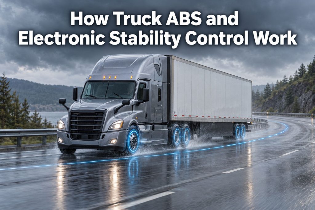
Modern commercial trucks use electronic braking systems to help drivers maintain wheel control and vehicle stability during hard braking, low-traction conditions, sudden steering maneuvers, and other situations where a heavy vehicle may begin to skid, jackknife, or roll over.
Antilock braking systems, commonly called ABS, monitor wheel speed and automatically regulate brake pressure when a wheel approaches lockup. Electronic stability control, commonly called ESC, uses additional sensors to compare the driver’s intended direction with the truck’s actual movement.
When an ESC system detects developing directional instability or rollover risk, it can reduce engine torque and selectively apply individual brakes to help stabilize the vehicle.
These technologies support the driver, but they cannot overcome excessive speed, poor tires, improperly secured cargo, unsafe loading, inadequate following distance, or poorly maintained foundation brakes.
This guide explains how truck ABS and electronic stability control work, how they differ, what components they use, and how they interact with tractors, trailers, air brakes, traction control, and collision-mitigation systems.
The Electronic Braking System
A modern commercial-truck electronic braking system can include:
- Antilock braking system
- Automatic traction control
- Electronic stability control
- Roll-stability control
- Trailer roll-stability system
- Electronic brake control
- Collision-mitigation braking
- Automatic emergency braking
- Electronic parking-brake controls
- Brake warning and diagnostic systems
These systems do not replace the truck’s mechanical foundation brakes.
Instead, they monitor vehicle behavior and electronically control the air pressure delivered to selected Air Disc Brake Systems or Drum Brake Systems.
What Is Truck ABS?
ABS is an electronic system designed to help prevent excessive wheel slip and wheel lock during braking.
When a wheel locks, it stops rotating even though the vehicle is still moving. A locked tire slides across the road instead of rolling.
This can reduce directional control and create:
- Longer or inconsistent stopping distances
- Steering-control problems
- Tire damage
- Flat-spotted tires
- Trailer instability
- Increased jackknife risk
- Loss of lateral traction
ABS monitors wheel rotation and adjusts brake pressure when it detects that a monitored wheel is decelerating too rapidly or beginning to lock.
Major ABS Components
A commercial-truck ABS commonly includes:
- Electronic control unit
- Wheel-speed sensors
- Tone rings or exciter rings
- ABS modulator valves
- Electrical wiring
- Connectors
- Power supply
- ABS warning lamp
- Diagnostic communication circuits
- Foundation brakes
- Air brake valves and chambers
Each component performs a different function.
Electronic Control Unit
The electronic control unit, or ECU, processes wheel-speed information and controls the ABS modulator valves.
The ECU continually compares wheel behavior to determine whether one or more wheels are approaching lockup.
Wheel-Speed Sensors
Wheel-speed sensors monitor the rotation of selected wheels.
A sensor is positioned near a toothed or magnetically encoded ring that rotates with the wheel or hub. As the ring passes the sensor, it produces an electrical signal that represents wheel speed.
Tone Rings
A tone ring—also called an exciter ring—provides the repeating pattern read by the wheel-speed sensor.
Damage, corrosion, contamination, incorrect sensor clearance, or excessive wheel-end movement can interfere with the signal.
ABS Modulator Valves
Modulator valves control air pressure to selected brake chambers during an ABS event.
Depending on the system, a modulator can:
- Increase brake pressure
- Hold brake pressure
- Decrease brake pressure
The ECU cycles these actions rapidly to help keep the wheel rotating.
ABS Warning Lamp
The warning lamp alerts the driver when the system detects a fault.
A tractor and trailer normally have separate ABS warning functions because they use separate electronic control systems.
How ABS Works During Hard Braking
During a normal brake application, the ABS may not intervene at all.
The sequence changes when a monitored wheel approaches lockup:
- The driver presses the brake pedal.
- The Air Brake System sends pressure toward the brake chambers.
- Wheel-speed sensors report wheel rotation to the ABS ECU.
- The ECU detects that a wheel is decelerating faster than expected.
- The ECU commands the appropriate modulator valve to hold or reduce pressure.
- The wheel begins rotating more freely.
- The ECU allows pressure to increase again.
- This cycle repeats as needed while the driver continues braking.
The driver may feel or hear the ABS operating, but should continue controlling the vehicle and applying the brakes as appropriate for the situation.
What ABS Does Not Do
ABS does not:
- Create additional tire traction
- Eliminate the effects of ice, snow, gravel, or water
- Guarantee a shorter stop in every condition
- Replace safe following distance
- Correct worn-out brakes
- Repair an air leak
- Prevent every jackknife
- Prevent every rollover
- Steer the truck for the driver
- Make excessive speed safe
- Override the laws of physics
ABS can help preserve wheel rotation and directional control, but the available traction between the tires and road still determines what the vehicle can do.
Tractor ABS
A tractor ABS monitors selected tractor wheels and controls brake pressure on the tractor.
Depending on the design, the system may use:
- Four wheel-speed sensors and four modulator channels
- Six wheel-speed sensors and four modulator channels
- Six wheel-speed sensors and six modulator channels
- Another manufacturer-approved configuration
The system description is sometimes written using numbers such as 4S/4M or 6S/6M.
The first number identifies the number of wheel-speed sensors. The second identifies the number of controlled modulator channels.
A greater number of channels can allow more independent control, but the exact system architecture depends on the vehicle.
Trailer ABS
A commercial trailer normally has a separate ABS ECU, sensors, modulators, warning lamp, and wiring.
Common trailer configurations include:
- 2S/1M
- 2S/2M
- 4S/2M
- 4S/3M
The appropriate arrangement depends on the number of axles, axle spacing, suspension design, and manufacturer specifications.
The trailer receives electrical power from the tractor, but the trailer ABS independently monitors and controls the trailer brakes connected to its system.
Learn more about the pneumatic and electrical relationship in Tractor vs Trailer Brake Systems.
Tractor ABS vs Trailer ABS
| System Area | Tractor ABS | Trailer ABS |
|---|---|---|
| Vehicle controlled | Tractor | Trailer |
| Electronic controller | Tractor ABS or stability ECU | Trailer ABS ECU |
| Wheel-speed sensors | Mounted at tractor wheel ends | Mounted at trailer wheel ends |
| Modulator valves | Control tractor brakes | Control trailer brakes |
| Warning indication | Tractor instrument panel | Trailer-mounted warning lamp and applicable tractor communication |
| Electrical power | Tractor electrical system | Supplied through tractor-trailer electrical connection |
| Stability integration | May support ESC, traction control, and collision mitigation | May support trailer roll stability |
| Fault effect | Tractor ABS or related functions may become limited | Trailer ABS or trailer stability functions may become limited |
A tractor ABS does not replace trailer ABS, and a trailer ABS does not control the tractor’s foundation brakes.
ABS on Air Disc and Drum Brakes
ABS can operate with both major commercial-vehicle foundation-brake designs.
ABS With Air Disc Brakes
With Air Disc Brakes, the modulator controls air pressure to the chamber that operates the caliper.
ABS With Drum Brakes
With S-cam drum brakes, the modulator controls air pressure to the chamber that moves the pushrod, slack adjuster, camshaft, and brake shoes.
ABS controls application pressure. It does not directly correct:
- Excessive pushrod stroke
- Worn brake linings
- Worn pads
- Cracked drums
- Damaged rotors
- Seized calipers
- Worn camshaft bushings
- Contaminated friction material
- Incorrect brake adjustment
The foundation brakes must still be inspected and maintained.
What Is Automatic Traction Control?
Automatic traction control, commonly called ATC, uses ABS components to help control drive-wheel spin during acceleration.
ABS primarily manages wheel slip during braking. ATC primarily manages excessive drive-wheel speed during acceleration.
When a drive wheel begins spinning, ATC may:
- Reduce engine torque
- Apply the brake at the spinning wheel
- Use both engine and brake intervention
- Transfer usable driving force toward a wheel with better traction
ATC can be helpful on:
- Snow
- Ice
- Rain
- Gravel
- Mud
- Loose construction surfaces
- Uneven traction conditions
ATC cannot create traction where none is available.
ABS vs Traction Control
| System | Primary Condition | Typical Response |
|---|---|---|
| ABS | Wheel approaches lockup during braking | Modulates brake pressure |
| ATC | Drive wheel spins during acceleration | Reduces engine torque or applies a drive-wheel brake |
| ESC | Vehicle begins departing from intended path or approaches instability | Reduces engine torque and selectively applies brakes |
| Roll-stability control | Excessive rollover risk develops | Reduces speed and applies selected brakes |
These systems often share sensors, valves, electronic controllers, and communication networks.
What Is Electronic Stability Control?
Electronic stability control is designed to help reduce directional instability and rollover risk.
ABS primarily evaluates wheel behavior. ESC evaluates the movement of the complete vehicle.
The system compares:
- Where the driver is attempting to steer
- How fast the truck is traveling
- How the truck is rotating
- How strongly it is moving sideways
- Whether the actual path matches the intended path
- Whether vehicle movement suggests rollover risk
If actual movement does not match the driver’s intended direction, ESC can intervene.
Major Electronic Stability Control Components
A heavy-truck ESC system may include:
- ABS or stability electronic control unit
- Steering-angle sensor
- Yaw-rate sensor
- Lateral-acceleration sensor
- Wheel-speed sensors
- Brake-pressure sensors
- ABS modulator valves
- Engine control module connection
- Vehicle communication network
- Stability-control warning lamp
- Foundation brakes
The system may also receive information from the transmission, engine brake, cruise-control system, and other vehicle electronics.
Steering-Angle Sensor
The steering-angle sensor tells the ESC system how the driver is positioning the steering wheel.
This helps the controller estimate the driver’s intended direction.
A steering-angle sensor may require calibration after:
- Steering-system repairs
- Alignment work
- Sensor replacement
- Steering-column service
- Electronic control replacement
- Certain chassis repairs
Incorrect calibration can affect system performance or trigger warning lamps.
Yaw-Rate Sensor
Yaw describes rotation around the vehicle’s vertical axis.
A yaw-rate sensor measures how quickly the truck is rotating left or right.
The ESC system compares measured rotation with the movement expected from steering input and vehicle speed.
Too much or too little yaw can indicate that the vehicle is not following the intended path.
Lateral-Acceleration Sensor
The lateral-acceleration sensor measures side-to-side force as the truck turns or changes direction.
High lateral acceleration can indicate increasing rollover risk, especially when combined with:
- Excessive speed
- A sharp curve
- Sudden steering
- A high center of gravity
- Improper loading
- Cargo movement
- Uneven road surfaces
The sensor’s information helps the stability controller decide whether intervention is needed.
How Electronic Stability Control Works
A simplified ESC intervention follows this sequence:
- The driver turns the steering wheel.
- The steering-angle sensor reports the intended direction.
- Wheel-speed sensors report vehicle and wheel behavior.
- Yaw and lateral-acceleration sensors report actual vehicle movement.
- The controller compares intended and actual movement.
- The system identifies developing directional instability or rollover risk.
- Engine torque may be reduced.
- Selected tractor brakes may be applied.
- Depending on the system, trailer brakes may also be commanded.
- The system continues monitoring until the vehicle stabilizes or the event ends.
ESC can react faster than a driver can individually control the brakes at separate wheel positions.
Understeer and Oversteer
ESC can help address two major directional-instability conditions.
Understeer
Understeer occurs when the truck does not turn as sharply as the driver intends.
The vehicle tends to continue toward the outside of the curve.
Possible contributing factors include:
- Excessive entry speed
- Low front-tire traction
- Wet or icy roads
- Steering too sharply
- Improper loading
- Tire problems
Oversteer
Oversteer occurs when the truck rotates more sharply than the driver intends.
The rear of the tractor may begin moving outward, increasing the risk of a spin or jackknife.
Possible contributing factors include:
- Excessive speed
- Sudden steering
- Low rear-tire traction
- Aggressive braking
- Improper loading
- Trailer forces
- Split-traction surfaces
ESC may apply selected brakes and reduce engine torque to help bring actual vehicle movement closer to the driver’s intended path.
Rollover Stability Control
Rollover stability control is designed primarily to help reduce rollover risk.
It monitors factors such as:
- Vehicle speed
- Lateral acceleration
- Steering activity
- Wheel behavior
- Brake application
- Estimated rollover threshold
When rollover risk increases, the system can reduce engine torque and apply brakes to slow the vehicle.
Reducing speed reduces the lateral forces acting on the truck during a turn.
ESC vs Roll-Stability Control
Electronic stability control and roll-stability control are related, but they are not identical.
| Feature | Electronic Stability Control | Roll-Stability Control |
|---|---|---|
| Directional stability | Yes | May be limited |
| Rollover intervention | Yes | Yes |
| Steering-angle input | Generally used | May not be used in every system |
| Yaw-rate measurement | Generally used | May not be used in every system |
| Lateral-acceleration measurement | Used | Used |
| Individual brake control | Can selectively apply brakes | Applies brakes to reduce speed and rollover risk |
| Engine-torque reduction | Yes | Commonly included |
| Helps address understeer and oversteer | Yes | Not its primary function |
System names and capabilities vary by manufacturer.
Trailer Roll-Stability Systems
Some trailers use independent roll-stability systems.
A trailer roll-stability system may monitor:
- Trailer wheel speed
- Lateral acceleration
- Brake pressure
- Trailer loading estimates
- Developing rollover conditions
When the system detects excessive rollover risk, it can apply the trailer brakes to reduce combination speed.
A trailer-based system can provide protection when the trailer is connected to different compatible tractors, but it does not replace tractor ESC.
Jackknife Prevention
A jackknife can occur when the tractor and trailer rotate toward each other at an unsafe angle.
Contributing factors can include:
- Drive-wheel lock
- Trailer-wheel lock
- Excessive speed
- Sudden steering
- Low traction
- Brake imbalance
- Improper loading
- Aggressive braking
- Trailer pushing against the tractor
ABS helps reduce wheel lock. ESC can detect developing directional instability and apply selected brakes.
These systems can reduce risk, but they cannot prevent every jackknife.
How ESC Uses the Brakes
ESC does not simply apply every brake equally.
Depending on the instability, the system may:
- Apply one steer-axle brake
- Apply selected drive-axle brakes
- Apply multiple tractor brakes
- Request trailer braking
- Reduce engine torque
- Coordinate braking with the transmission or engine brake
- Use different pressure at different wheel ends
Selective braking creates forces that can help counter unwanted vehicle rotation or reduce speed before rollover forces become more severe.
Engine-Torque Reduction
Braking is only one part of stability intervention.
The ESC controller may communicate with the engine control module and request a reduction in engine torque.
This can involve:
- Reducing fueling
- Limiting throttle response
- Canceling cruise-control demand
- Coordinating with the transmission
- Modifying engine-brake operation where appropriate
Reducing propulsion force helps prevent the driver’s throttle input from worsening an unstable condition.
ABS and Engine Brakes
Engine brakes and retarders help control speed without relying entirely on the foundation brakes.
However, strong engine braking on a low-traction surface can contribute to drive-wheel slip.
Modern electronic systems may coordinate:
- Engine brake
- Transmission
- ABS
- Traction control
- Stability control
- Cruise control
If drive-wheel slip is detected, the system may reduce retarding force to help restore wheel rotation.
Drivers must follow the vehicle manufacturer’s recommendations for engine-brake use in slippery conditions.
ABS and Collision-Mitigation Systems
Collision-mitigation and automatic emergency-braking systems may use radar, cameras, or other sensors to detect potential forward collisions.
These systems can:
- Warn the driver
- Reduce engine torque
- Precharge the braking system
- Apply partial braking
- Apply emergency braking
- Coordinate with ESC and ABS
- Help maintain stability during intervention
ABS manages wheel slip during the braking event. ESC helps manage vehicle stability. The collision-mitigation system determines when forward-collision intervention may be needed.
They are connected technologies, but they perform different jobs.
What the ABS Warning Lamp Means
When the ignition is turned on, the ABS warning lamp normally illuminates as part of a system check.
The lamp should then respond according to the manufacturer’s specified sequence.
A lamp that remains on can indicate:
- Wheel-speed sensor fault
- Incorrect sensor clearance
- Damaged tone ring
- Broken wiring
- Corroded connector
- Modulator-valve problem
- ECU fault
- Power-supply problem
- Communication failure
- Stored diagnostic code
The mechanical brakes may still apply, but the ABS function may be limited or unavailable.
The vehicle should be diagnosed using the appropriate service information.
What the ESC Warning Lamp Means
An ESC or stability-control lamp may illuminate briefly during system initialization or flash during an active intervention.
A lamp that remains illuminated may indicate:
- Disabled stability function
- Sensor calibration problem
- Steering-angle sensor fault
- Yaw or lateral-acceleration sensor fault
- ABS fault
- Communication problem
- Brake-pressure sensor fault
- Modulator-valve problem
- Electrical-power issue
- Stored diagnostic code
Because ESC depends on ABS components, an ABS fault may also disable or limit stability-control functions.
Common ABS Problems
Common ABS problems include:
- Damaged wheel-speed sensor wiring
- Excessive sensor gap
- Loose sensors
- Corroded connectors
- Damaged tone rings
- Metal debris on magnetic sensors
- Wheel-bearing movement
- Modulator-valve faults
- Low voltage
- Poor grounds
- Trailer power loss
- Communication-network faults
- Incorrect replacement components
- Unresolved diagnostic codes
The warning lamp should not simply be reset without correcting the underlying problem.
Common ESC Problems
Common electronic stability-control problems include:
- Steering-angle sensor miscalibration
- Yaw-sensor faults
- Lateral-acceleration sensor faults
- Incorrect sensor mounting
- ABS component failure
- Brake-pressure sensor problems
- Vehicle communication faults
- Incorrect tire sizes
- Chassis modifications
- Improper suspension changes
- Incorrect axle configuration data
- Electrical-power problems
- Faulty control modules
ESC depends on accurate information about vehicle configuration and movement.
How Tires Affect ABS and ESC
ABS and ESC can only work through the traction available at the tires.
System performance can be affected by:
- Low tread depth
- Incorrect inflation
- Mismatched tire sizes
- Uneven tire wear
- Damaged tires
- Different tire circumferences
- Poor traction
- Improper dual-tire matching
- Excessive wheel-end movement
Incorrect tire sizing can also cause wheel-speed differences that affect electronic-system calculations.
How Loading Affects Stability Control
Cargo weight and placement strongly affect vehicle stability.
Important factors include:
- Center-of-gravity height
- Side-to-side weight distribution
- Axle loading
- Cargo movement
- Liquid surge
- Suspended loads
- Partial tank loads
- Trailer length
- Load securement
- Gross combination weight
A high center of gravity increases rollover risk. Liquid tankers, car haulers, livestock trailers, double-deck equipment, and other specialized vehicles can have distinct stability characteristics.
ESC cannot make an improperly loaded or unsecured vehicle safe.
Driver Responsibilities During an ABS Event
During an ABS-assisted stop, the driver should:
- Maintain control of the steering wheel
- Continue braking as appropriate
- Look toward an escape path when one exists
- Avoid unnecessary steering inputs
- Allow the system to modulate pressure
- Adjust for road and traffic conditions
- Maintain awareness of trailer movement
- Follow the vehicle manufacturer’s operating instructions
Drivers should not assume that electronic intervention guarantees sufficient stopping distance.
Driver Responsibilities During an ESC Intervention
An active ESC intervention indicates that the vehicle may be approaching its stability limits.
The driver should:
- Reduce speed
- Avoid abrupt steering
- Avoid immediately reapplying heavy throttle
- Evaluate road conditions
- Consider load stability
- Increase following distance
- Inspect warning lamps
- Report unusual or repeated intervention
- Have the system inspected if intervention occurs during normal conditions
Frequent ESC activation may indicate excessive speed, aggressive driving, unstable loading, poor traction, sensor problems, or an equipment defect.
Inspecting ABS Components
An ABS inspection should include:
- Warning-lamp operation
- Wheel-speed sensors
- Sensor wiring
- Tone rings
- Modulator valves
- Electrical connectors
- Power and ground circuits
- Trailer electrical connection
- ECU mounting
- Diagnostic fault codes
- Air lines connected to modulators
- Foundation-brake condition
A complete brake inspection must still include the mechanical components described in How to Inspect and Maintain Commercial Truck Brakes.
Maintaining Electronic Braking Systems
Maintenance may include:
- Repairing damaged wiring
- Cleaning and repositioning wheel-speed sensors
- Replacing damaged tone rings
- Correcting wheel-bearing movement
- Repairing corroded connectors
- Replacing defective modulator valves
- Calibrating steering-angle sensors
- Verifying yaw-sensor mounting
- Correcting configuration data
- Updating approved control-module software
- Retrieving and documenting diagnostic codes
- Performing manufacturer-required verification tests
Electronic diagnosis should be performed by qualified personnel using the correct diagnostic equipment and service information.
Why Mechanical Brake Condition Still Matters
ABS and ESC control brake pressure, but the mechanical components create the actual friction that slows the vehicle.
Electronic systems cannot compensate fully for:
- Worn brake pads
- Worn linings
- Cracked drums
- Damaged rotors
- Oil-contaminated friction material
- Seized calipers
- Excessive pushrod stroke
- Broken springs
- Damaged chambers
- Major air leaks
- Missing brake components
A properly functioning ECU cannot make a defective foundation brake perform normally.
ABS, ESC, and Maintenance Records
Fleet records should document:
- Warning-lamp reports
- Diagnostic codes
- Sensor replacements
- Wiring repairs
- Modulator-valve service
- Calibration procedures
- Software or configuration updates
- Repeated faults
- Roadside-inspection findings
- Driver complaints
- Post-repair verification
Repeated faults at the same wheel position may indicate wiring routing, connector exposure, bearing movement, tone-ring damage, or another underlying problem.
Final Thoughts
ABS and electronic stability control perform different but connected functions.
ABS monitors wheel speed and modulates brake pressure when a wheel approaches lockup. This helps preserve wheel rotation and directional control during hard braking or low-traction conditions.
Automatic traction control uses many of the same components to manage drive-wheel spin during acceleration.
Electronic stability control monitors the movement of the complete vehicle. It compares steering input with wheel speed, yaw, and lateral acceleration to identify developing directional instability or rollover risk.
When intervention is required, ESC can reduce engine torque and selectively apply individual tractor or trailer brakes.
These systems can significantly support driver control, but they do not replace safe speed, proper loading, adequate following distance, good tires, trained drivers, or correctly maintained air and foundation brakes.
Continue Exploring Commercial Truck Brake Systems
Explore these related Truck Equipment Atlas pages:
- Brake Systems
- Air Brake Systems
- Air Disc Brake Systems
- Drum Brake Systems
- Brake Chambers and Actuators
- ABS and Electronic Braking Systems
- Trailer Brake Systems
- Air Brake Systems Explained
- Air Disc Brakes vs Drum Brakes
- How to Inspect and Maintain Commercial Truck Brakes
- Tractor vs Trailer Brake Systems
- Brake System Guides