
Quick Facts
- Manufacturer: ZF Commercial Vehicle Solutions, originally TRW Commercial Steering Systems
- Product Series: TAS Series
- Product Type: Integral hydraulic power-steering gear
- Common Models: TAS40, TAS55, TAS65, TAS66, and TAS85
- Steering Assistance: Hydraulic power assistance with mechanical steering capability
- Control Type: Rotary hydraulic control valve
- Output Connection: Sector shaft connected to the pitman arm
- Input Connection: Steering-column intermediate shaft
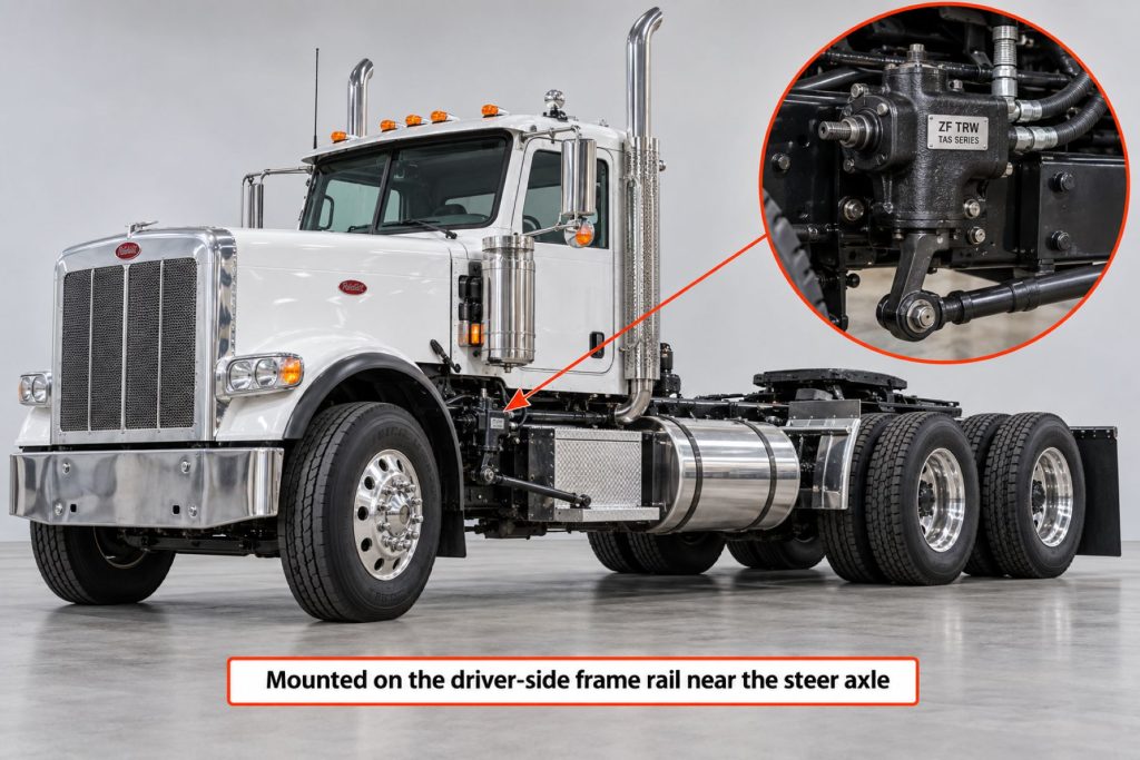
- Installation Position: Mounted to the vehicle frame near the steer axle
- Primary Applications: Medium-duty trucks, heavy-duty trucks, buses, fire apparatus, refuse vehicles, construction trucks, and specialty commercial vehicles
- Production Status: Application and service-parts availability depend on the exact model, specification number, and vehicle
Overview
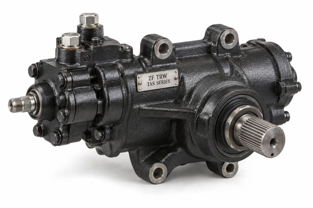
The ZF TRW TAS Series Steering Gear is an integral hydraulic power-steering system used on medium-duty and heavy-duty commercial vehicles. The gear converts steering-wheel movement into controlled movement of the pitman arm and steering linkage while using hydraulic pressure to reduce driver effort.
The TAS design combines a mechanical steering mechanism, rotary hydraulic control valve, and hydraulic power cylinder within a compact housing. This arrangement allows hydraulic assistance during normal operation while retaining limited manual steering capability if hydraulic assistance is lost.
TAS gears were produced in multiple capacities and configurations. The complete specification number is necessary when identifying replacement gears, seals, sector shafts, input components, mounting arrangements, and service parts.
Key Characteristics
- Integral hydraulic power-steering design
- Mechanical steering mechanism inside the gear
- Rotary hydraulic control valve
- Integrated hydraulic power cylinder
- Multiple models for different front-axle loads and vehicle applications
- Torsion-bar valve centering
- Controlled road feel and steering response
- Balanced-area cylinder design
- Manual steering capability following hydraulic-assist loss
- Optional pressure-relief features on applicable configurations
- Auxiliary hydraulic-cylinder porting available on certain gears
- Automatic poppet valves limit hydraulic pressure near steering stops
- High-temperature sealing components
- Application-specific sector shafts, ratios, mounts, and port arrangements
Major Components
- Steering-gear housing
- Input shaft
- Torsion bar
- Rotary control valve
- Valve housing
- Worm shaft
- Ball nut and recirculating balls
- Hydraulic piston
- Rack teeth
- Sector shaft
- Sector-shaft bearings
- Sector-shaft seals
- Input-shaft seals
- High-pressure inlet port
- Hydraulic return port
- Auxiliary-cylinder ports when equipped
- Automatic poppet valves
- Pressure-relief valve when equipped
- Adjuster and locking hardware
- Frame-mounting bosses
- Pitman-arm connection
Product Type and Construction
The TAS Series is an integral steering gear because its mechanical steering components, hydraulic control valve, and hydraulic power cylinder are contained within one housing.
The cast housing supports the input shaft, worm mechanism, piston, recirculating balls, sector shaft, bearings, seals, hydraulic passages, and mounting points. Individual gears differ in housing size, sector-shaft dimensions, ratio, travel, mounting orientation, and hydraulic-port arrangement.
How the Driveline or Steering Component Works
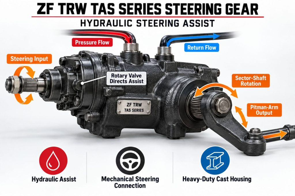
When the driver turns the steering wheel, the steering column rotates the gear’s input shaft. Input torque twists the torsion bar slightly and moves the rotary control valve away from its centered position.
The valve directs pressurized hydraulic fluid to one side of the internal piston while allowing fluid from the opposite side to return to the reservoir. Hydraulic pressure moves the piston, and the piston’s rack teeth rotate the sector shaft.
The sector shaft moves the pitman arm, drag link, steering arms, and tie rod to turn the steer wheels. When the driver stops applying steering input, the torsion bar helps recenter the valve and reduce hydraulic assistance.
Position and Function Within the Vehicle
The TAS gear is normally mounted to the vehicle frame near the steer axle. Its input shaft connects to the steering column through an intermediate steering shaft, while its sector shaft connects to the pitman arm.
The gear multiplies driver input, supplies hydraulic steering assistance, controls steering-linkage movement, and helps maintain a mechanical connection between the steering wheel and steer wheels.
Common Specifications
- Steering-Gear Type: Integral hydraulic power steering
- Common Series: TAS40, TAS55, TAS65, TAS66, and TAS85
- Hydraulic-Control Design: Rotary control valve
- Mechanical Conversion: Recirculating-ball worm, piston rack, and sector shaft
- Output Connection: Application-specific sector shaft and pitman arm
- Hydraulic Connections: Pressure inlet and return ports with auxiliary ports on applicable models
- Steering Stops: Axle stops with automatic hydraulic poppet-valve adjustment
- Maximum Seal Temperature: High-temperature seals were developed for temperatures up to approximately 250 degrees Fahrenheit
- Mounting: Application-specific frame mounting
- Steering Ratio: Model- and specification-specific
- Operating Pressure and Flow: Vehicle- and specification-specific
Exact pressure, flow, ratio, travel, sector-shaft, port, and mounting specifications must be confirmed from the complete TAS specification number.

Operating Capacity and Performance
TAS gear capacity depends on the model, steering ratio, sector-shaft size, hydraulic pressure, pump flow, front-axle loading, tire size, steering geometry, and vehicle application.
The correct TAS gear should be capable of steering the vehicle within its approved front-axle rating at low speed without exceeding hydraulic-system or mechanical-component limits.
Installation Position and System Function
The steering gear is mounted to the frame in a position that aligns its input shaft with the steering column and its sector shaft with the pitman arm and drag link.
Mounting position affects steering-column angles, pitman-arm movement, hydraulic-hose routing, axle clearance, and steering-linkage geometry. Replacement gears must match the original mounting orientation and travel direction.
Torque Transfer or Steering-Assist Function
The TAS Series converts steering-wheel torque into sector-shaft movement while hydraulic pressure supplies most of the force needed to turn the steer wheels.
The torsion bar regulates assistance according to steering effort. Greater resistance at the steer wheels causes additional torsion-bar deflection and increased hydraulic assistance.
Driveline Geometry and Operating Angles
Driveline angles do not directly control the TAS gear. However, engine, transmission, suspension, and frame changes can alter hydraulic-pump alignment, steering-shaft routing, and available clearance around the steering gear.
Steering Geometry and Movement
The TAS gear must work with the vehicle’s pitman arm, drag link, steering arms, tie rod, axle stops, caster, camber, toe, and steering-column geometry.
Improper pitman-arm indexing, incorrect steering stops, a shifted axle, bent linkage, or incorrect gear centering can cause unequal turning radius, tire interference, overtravel, or poor return-to-center performance.
Slip, Articulation, and Operating Travel
The TAS gear itself does not use a driveline-style slip joint. Steering-column intermediate shafts may use slip sections and universal joints to accommodate cab movement and installation geometry.
Sector-shaft travel must correspond with the axle stops and steering linkage. The internal poppet valves should unload hydraulic pressure just before the axle reaches its mechanical steering stops.
Bearings, Joints, Shafts, Gears, and Structural Design
The TAS gear uses an input shaft, torsion bar, rotary valve, recirculating-ball worm mechanism, hydraulically assisted piston, rack teeth, sector shaft, bearings, seals, and structural housing.
Steering force passes from the steering column through the input and worm mechanism to the piston and sector shaft. The sector shaft transfers this force through the pitman arm to the external steering linkage.
Materials and Component Construction
The gear uses a heavy cast housing with hardened and precision-machined internal components. High-temperature seals, bearings, recirculating balls, hydraulic passages, and external seal protectors support operation in commercial-vehicle environments.
Housing design, mounting bosses, sector-shaft dimensions, input-shaft configuration, and hydraulic-port locations vary among TAS specifications.
Hydraulic and Electric Steering Assistance
The TAS Series uses hydraulic assistance supplied by an engine-driven or otherwise approved power-steering pump. Pressurized fluid travels from the pump to the steering gear and returns through the reservoir and filtration circuit.
The TAS is not an electric power-steering gear. Vehicles using electronic steering-assistance or lane-keeping systems may add external actuators, overlays, or control systems while retaining the hydraulic gear.
Electronic Controls and Driver-Assistance Integration
The basic TAS gear operates mechanically and hydraulically without a dedicated electronic controller. Advanced driver-assistance systems may interact with the steering through separate torque-overlay devices, steering-column sensors, lane-keeping actuators, or electronic control modules.
Any added electronic system must be compatible with the steering gear, steering-column geometry, hydraulic assistance, vehicle network, and safety requirements.
Speed, Torque, and Load Management
Steering effort increases during low-speed maneuvering, high front-axle loading, operation on high-traction surfaces, and use of wide or underinflated tires.
The hydraulic pump must deliver the required pressure and flow without excessive heat. Holding the steering system against its mechanical stops for extended periods can generate heat and place unnecessary load on the pump and gear.
Vibration, Balance, and Noise Control
Driveshaft balance does not apply to the steering gear, but looseness or vibration can affect steering feel. Gear lash, worn linkage, loose frame mounts, damaged steering shafts, hydraulic aeration, and pump pulsation can create noise or steering-wheel movement.
Groaning commonly indicates hydraulic restriction, low fluid, aeration, pump wear, or excessive steering load. Clunking may indicate loose mounting hardware, sector-shaft wear, pitman-arm movement, or linkage wear.
Lubrication, Sealing, and Contamination Protection
The TAS gear is lubricated by the vehicle’s power-steering fluid. Input-shaft, sector-shaft, valve-housing, and internal seals retain fluid and prevent contamination.
Clean fluid, correct filtration, proper reservoir maintenance, and sealed hose connections are essential. Dirt or metallic debris can damage the valve, piston, bearings, seals, pump, and other hydraulic components.
Duty Cycle and Operating Conditions
TAS steering gears are used across highway, regional, delivery, bus, refuse, fire, construction, utility, and severe-service applications.
Frequent low-speed maneuvering, stationary steering, heavy front-axle loads, wide tires, high ambient temperatures, contamination, and vocational operation can increase hydraulic temperature and steering-system wear.
Mounting and Installation
The replacement gear must match the original frame-mounting pattern, orientation, input-shaft connection, sector shaft, pitman arm, steering ratio, travel, hydraulic ports, and hose arrangement.
The gear should be centered before the pitman arm and steering linkage are connected. Hydraulic hoses must be correctly routed, protected from heat and abrasion, and tightened using approved procedures.
Alignment, Driveline, and Mounting Geometry
The steering gear must be securely mounted to an undamaged frame or approved mounting bracket. Loose fasteners, cracked brackets, frame damage, or elongated mounting holes can cause steering movement and poor control.
After installation, technicians should verify steering-wheel position, intermediate-shaft alignment, pitman-arm indexing, steering-linkage geometry, axle stops, poppet adjustment, front-end alignment, and full-turn clearance.
Vehicle, Transmission, Axle, and Steering Compatibility
Compatibility depends on the vehicle manufacturer, model, frame, front axle, axle rating, tire size, steering linkage, steering-column connection, hydraulic pump, operating pressure, fluid-flow requirements, and original steering specification.
The TAS model number alone is not sufficient for replacement. The complete steering-gear specification number must be used because gears within the same series can have different ratios, shafts, ports, travel, and mounting configurations.
Related Component and System Compatibility
The TAS gear must be compatible with the power-steering pump, reservoir, filter, fluid, pressure and return hoses, steering column, intermediate shaft, pitman arm, drag link, steering arms, tie rod, front axle, and steering stops.
Vehicles using an auxiliary steering cylinder require the correct ported gear, hydraulic routing, cylinder size, mounting geometry, and flow capacity.
Common Applications
- Class 6 and Class 7 trucks
- Class 8 highway tractors
- Regional-haul trucks
- Delivery vehicles
- Transit buses
- School buses
- Motor coaches
- Fire and rescue apparatus
- Refuse trucks
- Construction trucks
- Utility vehicles
- Concrete mixers
- Dump trucks
- Specialized vocational vehicles
Advantages
- Integrated mechanical and hydraulic steering functions
- Reduces driver steering effort
- Multiple sizes for different commercial-vehicle applications
- Torsion bar provides valve centering and road feel
- Balanced hydraulic-cylinder design supports steering stability
- Manual steering connection remains following assist loss
- Automatic poppet valves reduce pressure near steering stops
- Auxiliary-cylinder porting available on applicable gears
- High-temperature sealing system
- Established service and remanufacturing support
- Used across a wide range of truck and bus applications
Limitations or Considerations
- Requires a properly functioning hydraulic pump and fluid circuit
- Hydraulic leaks can reduce assistance and create contamination
- Air in the system can cause noise and inconsistent steering
- Incorrect poppet adjustment can overload the hydraulic system
- Holding the steering against its stops creates heat
- The complete specification number is required for replacement
- Internal adjustment requires approved procedures
- Improper sector-shaft adjustment can create binding or excessive play
- Frame damage or loose mounting hardware affects steering control
- Manual steering after assist loss requires significantly greater effort
- Some configurations may be legacy products
Driver and Operator Experience
A correctly operating TAS gear should provide smooth assistance, predictable response, controlled road feel, and consistent steering effort. The wheel should return toward center after a turn when the vehicle’s alignment and steering geometry are correct.
Drivers should report increased steering effort, looseness, binding, wandering, delayed response, hydraulic noise, fluid leakage, poor return-to-center behavior, or a steering wheel that no longer remains centered.
Steering Feel and Driver Feedback
The torsion bar helps provide a defined relationship between driver input and hydraulic assistance. This allows the driver to retain some road feel while receiving the assistance needed to turn a heavily loaded commercial-vehicle steer axle.
Steering that feels excessively light, heavy, notchy, loose, delayed, or inconsistent may indicate problems in the gear, pump, hoses, steering column, linkage, axle, tires, or alignment.
Operating Speed, Angle, and Load Management
The steering system experiences its highest hydraulic loads during low-speed or stationary steering. Drivers should avoid holding the steering wheel firmly against the stops because this can generate excessive pressure and heat.
- Maintain correct front-tire inflation
- Avoid prolonged steering against the axle stops
- Reduce unnecessary stationary steering
- Report sudden increases in steering effort
- Inspect the system after curb or collision impacts
- Confirm correct axle loading
- Monitor hydraulic-fluid level and condition
Control Setup and System Calibration
The basic TAS gear does not require electronic calibration. Mechanical centering, pitman-arm indexing, axle-stop adjustment, sector-shaft adjustment, and automatic poppet setting must be completed correctly.
Vehicles with lane-keeping or steering-assistance technology may require electronic sensor calibration after steering-gear, steering-column, alignment, or linkage service.
Inspection and Wear Points
- Steering-gear housing
- Frame and mounting bracket
- Mounting bolts and holes
- Input shaft and input seal
- Intermediate steering shaft
- Sector shaft and sector-shaft seals
- Pitman-arm connection
- Sector-shaft adjustment
- Pressure and return ports
- Hydraulic hoses and fittings
- Auxiliary-cylinder ports when equipped
- Fluid leaks and contamination
- Steering free play
- Binding through the steering range
- Axle stops and poppet operation
Lubrication Requirements
The TAS gear is lubricated internally by approved power-steering fluid. The steering linkage, steering shaft, pitman arm, drag link, and other external components may have separate lubrication requirements.
Only fluid approved for the vehicle and steering system should be used. Mixing incompatible fluids can damage seals, reduce lubrication, and change steering performance.
Component Service Life and Rebuildability
TAS steering gears may be serviced or remanufactured by qualified facilities using approved procedures and replacement components. Available service operations can include seal replacement, bearing service, sector-shaft adjustment, poppet resetting, inspection, and complete rebuilding.
A gear with a cracked housing, damaged mounting surface, severely worn internal components, or collision damage may require complete replacement rather than normal repair.
Shaft, Joint, Bearing, Gear, and Linkage Service Life
Input-shaft, sector-shaft, bearing, worm, piston, and recirculating-ball life depends on fluid cleanliness, lubrication, adjustment, hydraulic pressure, vehicle loading, and steering-system condition.
Worn pitman-arm splines, drag-link ends, steering-shaft joints, kingpins, or tie-rod ends can produce symptoms resembling internal steering-gear wear.
Seal, Hose, Sensor, and Electronic Service Life
Input and sector-shaft seals can deteriorate from heat, contamination, shaft wear, pressure problems, or age. Hydraulic hoses can fail from abrasion, heat exposure, improper routing, movement, or internal deterioration.
The basic TAS gear contains no electronic sensors. Sensors associated with steering-wheel position, steering angle, lane keeping, or stability control are separate vehicle components.
Maintenance and Ownership Notes
Steering maintenance should address the complete hydraulic and mechanical system rather than the gear alone.
- Inspect the steering gear for fluid leakage
- Check frame mounts and fasteners
- Inspect the input and sector shafts
- Check pitman-arm attachment
- Inspect pressure and return hoses
- Maintain the correct fluid level
- Replace contaminated or incorrect fluid
- Service the reservoir filter as required
- Bleed air after opening the hydraulic system
- Inspect drag-link and tie-rod ends
- Check steering-column joints and slip connections
- Verify axle-stop and poppet operation
- Measure steering free play
- Investigate noise, binding, or increased effort promptly
Common Driveline and Steering Problems
- Heavy steering: Low fluid, pump wear, restricted hoses, incorrect flow, air in the system, excessive front-axle loading, linkage binding, or internal gear problems may increase effort.
- Excessive steering play: Sector-shaft adjustment, worn internal components, loose mounting hardware, pitman-arm wear, or loose steering linkage may cause free play.
- Hydraulic leakage: Input-shaft seals, sector-shaft seals, hose fittings, valve-housing seals, or damaged hoses may leak fluid.
- Poor return to center: Incorrect caster, binding linkage, excessive sector-shaft adjustment, steering-column binding, tire problems, or internal gear friction may be responsible.
- Steering wander: Gear lash, worn linkage, loose wheel bearings, kingpin wear, tire problems, alignment, frame movement, or suspension wear may cause wandering.
- Hydraulic groaning: Low fluid, aeration, pump cavitation, restrictions, contamination, or prolonged operation against the steering stops may cause noise.
- Unequal steering travel: Incorrect gear centering, pitman-arm indexing, axle-stop settings, linkage damage, or poppet adjustment can limit travel in one direction.
- Binding or notchy steering: Internal damage, incorrect adjustment, contaminated fluid, steering-shaft binding, or worn linkage may create inconsistent movement.
Safety and Service Precautions
Commercial-vehicle steering components are safety-critical. TAS steering gears should be inspected, adjusted, repaired, and installed by technicians trained to service heavy-vehicle steering systems.
- Secure the vehicle against movement before service
- Support the vehicle correctly when working beneath it
- Relieve hydraulic pressure before disconnecting hoses
- Wear eye protection when servicing hydraulic components
- Keep contaminants out of open hydraulic lines and ports
- Do not adjust the sector shaft to conceal worn components
- Use approved replacement seals, hardware, and internal parts
- Do not reuse damaged pitman arms or mounting hardware
- Bleed the hydraulic system after service
- Confirm full steering travel and clearance before road operation
- Complete an alignment when steering geometry has changed
Identification Information
The steering-gear specification number and date code are normally stamped into a machined surface on the housing opposite the input shaft. This identification should be recorded before ordering a replacement gear or service components.
- Vehicle identification number
- Vehicle manufacturer and model
- TAS series and model
- Complete steering-gear specification number
- Date code
- Steering ratio
- Input-shaft configuration
- Sector-shaft diameter and spline
- Housing and mounting pattern
- Hydraulic-port locations
- Auxiliary-cylinder porting
- Pitman-arm number
- Power-steering pump information
- Left-hand or right-hand installation
Buying Considerations
- Record the complete TAS specification number
- Confirm the TAS40, TAS55, TAS65, TAS66, or TAS85 series
- Match the frame-mounting pattern
- Verify input-shaft size and connection
- Match the sector-shaft spline and pitman arm
- Confirm steering ratio and total travel
- Match pressure and return port locations
- Determine whether auxiliary-cylinder ports are required
- Verify hydraulic pressure and flow requirements
- Check left-hand or right-hand mounting orientation
- Confirm front-axle rating and tire configuration
- Determine whether a new, remanufactured, or serviceable gear is appropriate
- Use a commercial-steering supplier familiar with TAS specifications
Variants and Configurations
- TAS40 steering gear
- TAS55 steering gear
- TAS65 steering gear
- TAS66 steering gear
- TAS85 steering gear
- Standard-bore configurations
- Step-bore configurations
- Different steering ratios
- Different sector-shaft sizes
- Different input-shaft configurations
- Different mounting orientations
- Different hydraulic-port arrangements
- Auxiliary-cylinder ported gears
- Optional pressure-relief configurations
- OEM and remanufactured replacement gears
Comparison to Similar Equipment
Compared with the ZF TRW THP Series Steering Gear, the TAS Series represents an earlier and widely established integral hydraulic steering-gear family. The THP Series is associated with later applications, faster steering-ratio options, and updated steering-response characteristics.
Compared with the planned ZF TRW PCF Series Steering Gear, a standard TAS gear does not provide the same Positive Center Feel characteristics. PCF configurations are designed to provide additional on-center steering feedback.
Compared with the planned Sheppard M Series Steering Gear, the TAS Series uses different internal components, mounting arrangements, hydraulic connections, adjustments, and application specifications.
Compared with electrically assisted steering systems, the TAS Series depends on conventional hydraulic pressure from the vehicle’s power-steering pump. Electronic safety and driver-assistance systems may still use steering-angle information elsewhere in the vehicle.
Best Fit For
- Vehicles originally equipped with a ZF TRW TAS steering gear
- Heavy-duty highway tractors
- Regional-haul trucks
- Vocational trucks
- Commercial buses
- Motorhomes and specialty commercial chassis
- Vehicles requiring hydraulic assistance for a heavily loaded steer axle
- Fleets maintaining established hydraulic steering systems
- Applications with an exact TAS specification-number match
Related Vehicle and Trailer Types
- Highway Tractors
- Class 6, Class 7, and Class 8 Trucks
- Heavy-Haul Tractors
- Dump Trucks
- Concrete Mixer Trucks
- Refuse Trucks
- Fire and Emergency Vehicles
- Commercial Buses
Related Truck and Trailer Models
- Freightliner Cascadia
- Freightliner M2 106
- Kenworth T680
- Kenworth T880
- Peterbilt 579
- Peterbilt 567
- International LT Series
- International HX Series
- Mack Anthem
- Mack Granite
- Volvo VNL
- Western Star 49X
Related Driveline and Steering System Types
- Steering Gears & Steering Linkage
- Power Steering Pumps & Hydraulic Assist
- Steering Columns & Driver Controls
- Advanced Steering & Lane-Keeping Systems
- Commercial Truck Driveshafts
- Universal Joints, Slip Yokes & Center Bearings
Related Driveline and Steering Products
- ZF TRW THP Series Steering Gear
- ZF TRW PCF Series Steering Gear
- ZF TRW RCH Series Steering Gear
- Sheppard M Series Steering Gear
- Bendix Reman TRW Steering Gear
- ZF TRW Power Steering Pump
- ZF ReAX Steering System
Related Equipment Systems
- Drivelines & Steering Systems
- Suspension Systems
- Axles & Differentials
- Tires & Wheels
- Brake Systems
- Electrical Systems
- Safety Systems
- Equipment Systems
Related Guides
- Driveline & Steering System Guides
- How Commercial Truck Steering Systems Work
- Hydraulic vs Electric-Assisted Commercial Truck Steering
- Common Commercial Truck Driveline Vibrations and Steering Problems
- Commercial Truck Steering Components Explained
- How to Inspect Commercial Truck Steering Systems
- Common Commercial Truck Power-Steering Problems
Regulatory and Compliance Notes
Commercial-vehicle steering systems must remain in safe operating condition and comply with applicable inspection, maintenance, and out-of-service requirements. Excessive steering free play, insecure mounting, damaged linkage, serious hydraulic leakage, cracked components, or interference may make a vehicle unsafe to operate.
Replacement or modification must preserve the vehicle’s approved steering geometry, axle ratings, tire clearance, linkage travel, frame integrity, and electronic safety-system operation. Local regulations, vehicle-manufacturer requirements, and fleet standards may impose additional restrictions.
Real World Operating Notes
Steering complaints should be diagnosed as complete-system problems. Tires, wheel bearings, kingpins, alignment, steering-column joints, pitman-arm splines, drag-link ends, tie-rod ends, hydraulic pumps, hoses, and frame mounting can all create symptoms that resemble steering-gear failure.
Low fluid or air trapped in the hydraulic circuit can cause noise, foaming, inconsistent assistance, overheating, and pump damage. Leaks should be corrected and the system properly bled before the steering gear is condemned.
Drivers should avoid holding the steering wheel against full lock. Extended full-lock operation raises hydraulic pressure and temperature while increasing demand on the pump, hoses, seals, steering gear, linkage, and tires.
Frequently Asked Questions
What is the ZF TRW TAS Series Steering Gear?
The TAS Series is a family of integral hydraulic power-steering gears used on heavy commercial trucks, buses, recreational vehicles, and specialty chassis.
How does a TAS steering gear work?
It combines driver input from the steering column with hydraulic pressure from the power-steering pump. Internal piston movement rotates the sector shaft and pitman arm, which operate the steering linkage.
Which TAS models are available?
The TAS family includes multiple application-specific models and specification numbers. The exact gear must be identified from the vehicle and the information stamped on the steering-gear housing.
Can a TAS steering gear be replaced with a THP gear?
Not automatically. Mounting, ratio, rotation, travel, input shaft, sector shaft, pitman arm, hydraulic ports, pressure, flow, and vehicle approval must all be verified.
Can the vehicle still steer if hydraulic assistance is lost?
The mechanical connection remains, but steering effort becomes substantially higher. The vehicle should be stopped safely and inspected before continued operation.
What causes heavy steering?
Possible causes include low fluid, trapped air, insufficient pump output, hydraulic restrictions, binding linkage, improper alignment, overloaded steer axles, underinflated tires, or internal gear wear.
What causes excessive steering free play?
Free play may come from steering-column joints, mounting hardware, pitman-arm splines, drag-link ends, tie-rod ends, kingpins, wheel bearings, or internal steering-gear wear.
Can a TAS steering gear be rebuilt?
Many TAS gears can be professionally remanufactured. Correct rebuilding requires specialized tools, approved components, precision measurements, adjustments, and functional testing.
How is the correct replacement gear identified?
Use the complete steering-gear specification number, vehicle identification number, mounting pattern, input and output configuration, hydraulic ports, rotation, pitman arm, and vehicle application.
Should the steering gear be adjusted to remove all free play?
No. The source of the free play must first be identified throughout the complete steering system. Steering-gear adjustments must follow the approved service procedure.
Availability and Where to Find
ZF TRW TAS steering gears, remanufactured assemblies, service components, seals, pitman arms, hoses, and related steering parts may be available through commercial-truck dealers, ZF and TRW distributors, heavy-duty parts suppliers, steering specialists, and professional remanufacturers.
Availability depends on the exact TAS model, specification number, mounting arrangement, input shaft, output rotation, sector shaft, hydraulic ports, vehicle application, and production status. All identification information should be verified before ordering.
Current product information, technical resources, and distributor support are available through the ZF Aftermarket website.
Support Trucking Families
Truck Equipment Atlas supports the mission of Grey Cross, a nonprofit dedicated to helping families of truck drivers who lose their lives while on the road. As the site grows, part of its mission is to bring awareness and support to these families.
Podcast or Video Section
Learn More Through Audio and Video
Truck Equipment Atlas will continue expanding with podcast episodes, interviews, and equipment breakdowns to help drivers and fleets better understand trucks and equipment.
Follow the Growth of Truck Equipment Atlas
Truck Equipment Atlas continues to expand with new truck profiles, trailer coverage, diesel engine pages, equipment system resources, manufacturer information, and educational guides.
Visit our Site Updates page to explore recent additions, project milestones, and upcoming resources as we continue building one of the industry’s growing commercial trucking equipment reference libraries.
View the Latest Site Updates: Truck Equipment Atlas Site Updates