
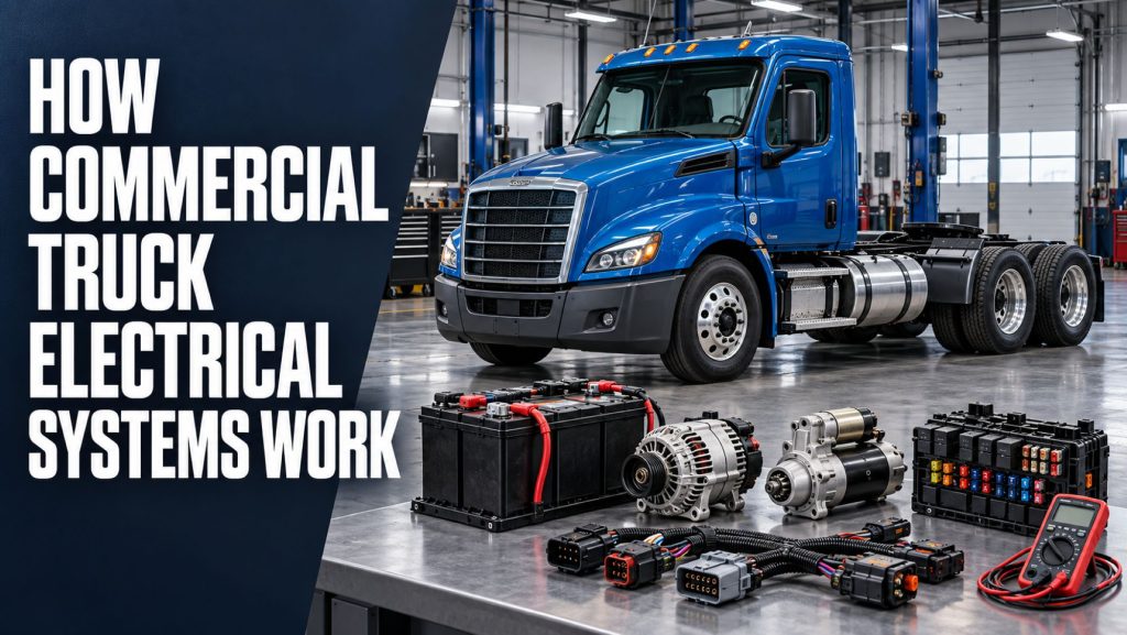
Commercial truck electrical systems provide the power, control, communication, and monitoring needed to start the engine, operate lighting, manage the powertrain, support safety systems, run cab accessories, and connect the tractor with a trailer. Even systems that appear primarily mechanical, hydraulic, or pneumatic increasingly depend on electrical sensors, electronic control units, wiring, and vehicle data networks.
A modern truck may contain multiple batteries, a high-output alternator, hundreds of electrical circuits, numerous control modules, and thousands of connection points. These components must operate in heat, cold, vibration, moisture, road salt, dust, and continuous commercial service.
This guide explains how commercial truck electrical systems work, the major components involved, how power and information move through the vehicle, common system configurations, warning signs, and important inspection and maintenance considerations. Readers can also explore the broader Electrical Systems section for related equipment information.
What a Commercial Truck Electrical System Does
The electrical system performs two broad jobs. It distributes electrical power to components that require energy, and it carries electronic information among sensors, switches, control modules, displays, and actuators.
- Stores electrical energy in the batteries
- Cranks the engine through the starting system
- Generates electrical power while the engine operates
- Maintains battery charge
- Distributes power through cables, wiring, fuses, relays, and control modules
- Operates exterior and interior lighting
- Supports engine, transmission, brake, steering, suspension, and emissions controls
- Powers cab accessories, HVAC controls, telematics, and communication equipment
- Transfers power and signals between tractors and trailers
- Monitors faults and supports electronic diagnostics
Electrical power and electronic communication are related but are not the same. A circuit may have adequate voltage yet still experience a communication fault, while a control network may function correctly even though a high-current starter or charging circuit has failed.
Basic Electrical Terms
| Term | Meaning | Why It Matters |
|---|---|---|
| Voltage | Electrical potential that pushes current through a circuit | Insufficient or excessive voltage can prevent components from operating correctly |
| Current | Flow of electrical charge, measured in amperes | High-current components require correctly sized cables and connections |
| Resistance | Opposition to electrical current, measured in ohms | Unwanted resistance creates voltage drop, heat, and weak component performance |
| Power | Rate of electrical energy use, measured in watts | Helps determine circuit load and charging-system demand |
| Ground | Return path from the electrical load to the battery | Poor grounds can cause starting, charging, lighting, sensor, and communication problems |
| Voltage drop | Voltage lost while current moves through a circuit | Excessive drop often identifies resistance in cables, terminals, switches, or grounds |
12-Volt and 24-Volt Truck Electrical Systems
Most conventional North American commercial trucks use a nominal 12-volt electrical system. Other commercial vehicles, military equipment, off-highway machines, buses, and equipment used in different markets may use 24-volt architecture or a combination of voltage levels.
System voltage affects battery arrangement, starter design, alternator output, lamps, relays, electronic modules, accessories, and service procedures. A component designed for one voltage must not be connected to another without an approved converter or manufacturer-designed interface.
Battery-electric and hybrid trucks may contain a conventional low-voltage system alongside a separate high-voltage traction system. The low-voltage system normally supports controls, lighting, communication, and accessory functions, while the high-voltage system supplies propulsion energy. High-voltage equipment requires specialized training, protective equipment, and isolation procedures.
Major Commercial Truck Electrical Components
Batteries
Batteries store chemical energy and release it as electrical power. They provide the high current needed to crank the engine and stabilize system voltage when electrical demand changes.
Heavy trucks commonly use multiple batteries connected as a bank. Batteries connected in parallel increase available current capacity while maintaining the same nominal voltage. Batteries connected in series increase system voltage. The correct arrangement depends on the vehicle design.
All batteries in a bank should be compatible in type, capacity, age, and condition. One weak or internally damaged battery can reduce cranking performance, create uneven charging, and shorten the life of the other batteries.
Battery Cables and Grounds
Battery cables carry high current between the battery bank, starter, alternator, disconnect switch, power-distribution points, frame, and engine. Because starting current is high, small amounts of resistance can produce significant voltage loss and heat.
A complete ground path may include battery-to-frame, battery-to-engine, engine-to-frame, cab-to-frame, and component-specific ground connections. Corrosion, loose fasteners, paint, damaged strands, undersized replacement cables, or poor routing can create difficult intermittent faults.
Starter Motor and Solenoid
The starter converts electrical energy into mechanical rotation. When the driver requests a start, a control circuit energizes a relay or starter solenoid. The solenoid connects battery power to the starter motor and moves the drive gear into engagement with the engine flywheel or ring gear.
The starter must overcome engine compression, oil resistance, internal friction, and cold-weather loads. Battery condition, cable resistance, ground quality, starter condition, engine temperature, oil viscosity, and mechanical engine condition all influence cranking speed.
Alternator
The alternator converts mechanical energy from the engine into electrical energy. A belt or gear drive turns the alternator rotor, creating alternating current inside the stator. Rectifier diodes convert that output into direct current for the truck’s electrical system.
A voltage regulator controls alternator output to maintain system voltage within the required range. Alternator capacity must be sufficient for lighting, HVAC blowers, engine controls, trailer loads, auxiliary equipment, cab accessories, and battery charging under the truck’s actual duty cycle.
Fuses, Circuit Breakers, and Fusible Links
Circuit-protection devices are designed to interrupt current when a circuit draws more than its safe limit. This helps protect wiring and components from overheating and fire.
A blown fuse is evidence of an open circuit, but it is not normally the underlying cause. Installing a larger fuse can allow wiring to overheat. The source of the overload, short circuit, damaged wiring, or failed component must be identified before returning the truck to service.
Relays and Solenoids
A relay allows a low-current control circuit to switch a higher-current load. Relays are commonly used for lights, fans, heaters, starter controls, pumps, horns, and accessory circuits.
Relay contacts can burn, stick, or develop excessive resistance. Coils can open or short, while sockets may corrode or lose terminal tension. Testing should confirm control power, ground, switched power, and load operation.
Wiring Harnesses and Connectors
Wiring harnesses organize insulated conductors into protected routes through the chassis, engine compartment, cab, and trailer. Loom, conduit, clips, grommets, seals, strain relief, and routing protect the wires from heat, abrasion, chemicals, sharp edges, and movement.
Connectors must maintain low-resistance electrical contact while preventing moisture and contamination from reaching the terminals. Loose locking tabs, spread terminals, damaged seals, poor repairs, corrosion, and water intrusion can create intermittent faults that change with vibration or weather.
Switches and Sensors
Switches communicate driver commands or component position. Sensors measure conditions such as pressure, temperature, speed, position, level, airflow, exhaust composition, wheel rotation, and vehicle motion.
Some sensors produce their own signal, while others depend on a reference voltage and ground supplied by a control module. A fault in shared reference-voltage or ground circuits can affect multiple sensors at the same time.
Electronic Control Units
Electronic control units process input signals, make programmed decisions, and command outputs. A modern truck may have separate controllers for the engine, transmission, brakes, body equipment, instrument panel, steering, aftertreatment, telematics, HVAC, doors, lighting, and other functions.
Control modules depend on stable power, clean grounds, correct sensor signals, compatible software, and reliable network communication. A module-related fault should not be assumed until its power supplies, grounds, connectors, inputs, outputs, and network condition have been tested.
How the Starting System Works
- The driver turns the key or presses the start control.
- The vehicle verifies required conditions such as neutral position, clutch position, security authorization, and available system voltage.
- A control module or start relay energizes the starter solenoid.
- The solenoid moves the starter drive into engagement and closes the high-current contacts.
- Battery current flows through the starter motor.
- The starter turns the engine crankshaft.
- The engine control system supplies fuel and manages starting.
- After the engine starts, the starter disengages and the alternator begins supporting the electrical system.
A no-crank condition and a crank-but-no-start condition are different problems. No crank directs attention toward batteries, cables, starter controls, the starter, interlocks, and mechanical resistance. Normal cranking without engine operation may involve fuel, engine control, sensor, communication, security, or mechanical faults.
How the Charging System Works
Once the engine is operating, the alternator supplies electrical power and replenishes energy removed from the batteries during starting. Alternator output changes with system demand, battery state of charge, temperature, engine speed, and regulator strategy.
When demand exceeds alternator output, the batteries temporarily supply part of the load. When alternator output exceeds immediate demand, current can recharge the batteries. A charging system must therefore be evaluated under realistic operating loads rather than by checking unloaded voltage alone.
Low charging voltage can result from a weak alternator, slipping drive, wiring resistance, poor grounds, failed batteries, excessive loads, or control problems. Excessive voltage can damage batteries, lamps, electronics, and accessories.
Power Distribution
Electrical power normally travels from the battery bank or alternator to main distribution points. From there, fuses, breakers, relays, switches, and electronic modules direct power to individual circuits.
Some circuits receive constant battery power. Others receive power only with the ignition switch in a specific position or when a control module activates a relay. Modern body controllers may replace several conventional switches and relays by electronically managing lighting and accessory outputs.
Power-distribution centers should remain dry, secured, correctly covered, and free from overheated terminals or unauthorized modifications. Added accessories should use properly sized wiring, circuit protection, grounds, and approved connection points.
Truck Lighting Systems
Commercial truck lighting includes headlamps, daytime running lamps, turn signals, hazard lamps, stop lamps, tail lamps, marker lamps, clearance lamps, identification lamps, license-plate lamps, work lights, instrument illumination, and interior lighting.
Many newer trucks use LED lighting because it can reduce current demand and extend service life. LED lamps still depend on sound connectors, grounds, seals, wiring, and compatible electronic controls. A low-current LED fault may also require different diagnostic methods than a conventional incandescent lamp.
Lighting problems may involve the lamp itself, but they can also result from a fuse, relay, switch, body controller, trailer connection, wiring fault, poor ground, or incompatible replacement component.
Tractor-to-Trailer Electrical Connections
A tractor supplies trailer electrical power and lighting signals through a commercial electrical connection. Depending on the vehicle and configuration, the connection may support tail lamps, marker lamps, stop lamps, turn signals, auxiliary power, trailer ABS, charging circuits, liftgate equipment, refrigeration controls, or other accessories.
The electrical cable and receptacles must flex as the tractor and trailer articulate while remaining clear of the deck, frame, exhaust, driveline, and coupling components. Damaged pins, corrosion, loose sockets, stretched cables, poor seals, and incorrect pin assignments can create lighting and ABS faults.
Trailer ABS receives electrical power from the tractor but uses its own controller, sensors, and modulator valves. The relationship between electronic power and pneumatic braking is explained further in How Truck ABS and Electronic Stability Control Work.
Vehicle Communication Networks
Modern trucks use communication networks to let electronic control units share information without running a separate signal wire for every function. Engine speed, vehicle speed, brake status, transmission gear, steering angle, temperatures, pressures, warning messages, and diagnostic information can be transmitted across these networks.
Controller Area Network, commonly called CAN, is widely used in commercial vehicles. Heavy-duty vehicles may also use industry-standard communication protocols that allow compatible controllers and diagnostic tools to exchange information.
A network fault may be caused by loss of power to one module, damaged twisted-pair wiring, connector corrosion, incorrect termination, a short to power or ground, electrical interference, or a failed controller. One fault can create multiple warning lamps because several systems depend on the missing information.
Electrical Integration With Other Truck Systems
Engine and Emissions Controls
The engine control module receives information from sensors and controls fueling, timing, turbocharger operation, cooling fans, engine protection, cruise control, idle management, and emissions equipment. Electrical faults can therefore create performance problems even when the engine’s mechanical components remain serviceable.
Transmission Controls
Automated manual and automatic transmissions depend on electronic controllers, speed sensors, position sensors, shift actuators, solenoids, and communication with the engine. Low voltage or network faults can affect starting authorization, gear selection, clutch operation, and shift quality. Learn more through the Transmission Guides.
Brake and Stability Systems
ABS, traction control, electronic stability control, and collision-mitigation systems use wheel-speed sensors, steering and motion sensors, electronic controllers, warning lamps, network communication, and electrically controlled valves. The foundation brakes remain pneumatic or mechanical, but electronic controls influence how and when braking force is applied.
The Air Brake Systems section explains the pneumatic components that work alongside these electronic controls.
Steering Systems
Steering-angle sensors, electronically controlled hydraulic pumps, electric-assist motors, lane-support systems, and stability controls connect steering functions to the truck’s electrical network. The guide How Commercial Truck Steering Systems Work explains the mechanical and power-assist components.
Suspension and Axle Systems
Electronically controlled suspensions, lift axles, tire-inflation systems, axle temperature sensors, traction systems, and electric drive axles all depend on electrical power and controls. Explore How Commercial Truck Suspension Systems Work and Electric Drive Axles for related information.
PTO and Hydraulic Equipment
Power take-offs and hydraulic equipment may use electric switches, interlocks, solenoids, pressure sensors, proportional controls, warning devices, and body-control modules. The electrical system may prevent PTO operation unless vehicle speed, transmission position, parking brake, engine speed, and other conditions are correct. Visit the PTO and Hydraulic System Guides for more information.
Cab, Sleeper, and Auxiliary Electrical Loads
Cab and sleeper equipment can create substantial electrical demand, especially when the engine is off. Common loads include HVAC blowers, bunk heaters, refrigerators, inverters, televisions, microwaves, lighting, charging ports, communications equipment, auxiliary power units, and hotel-load systems.
An inverter converts direct current from the batteries into alternating current for compatible appliances. Its input-current demand can be high, so cable size, fuse protection, ventilation, mounting, battery capacity, and low-voltage protection are important.
Battery-powered accessories must be managed so enough energy remains for starting. Low-voltage disconnects, dedicated auxiliary batteries, idle-management systems, and auxiliary power units may be used to protect starting capacity.
Common Electrical Problems and Warning Signs
| Symptom | Possible Areas to Investigate |
|---|---|
| No crank | Batteries, cables, grounds, disconnect switch, start relay, solenoid, starter, interlocks, control module |
| Slow cranking | Weak batteries, cable voltage drop, poor grounds, starter wear, cold oil, mechanical engine resistance |
| Repeated dead batteries | Battery condition, charging output, parasitic draw, accessory use, cable leakage, incorrect battery capacity |
| Low charging voltage | Alternator, drive belt, regulator, wiring resistance, grounds, batteries, excessive load |
| Lights dim or flicker | Charging system, grounds, connectors, relay contacts, wiring, lamp assemblies |
| Fuse repeatedly opens | Short circuit, overloaded circuit, damaged wiring, failed component, incorrect accessory installation |
| Multiple warning lamps | Low voltage, module power or ground loss, network fault, shared sensor circuit, charging problem |
| Intermittent fault over bumps | Loose terminal, rubbed wire, damaged connector lock, harness strain, poor ground |
| Hot cable or connector | Loose connection, corrosion, undersized conductor, excessive current, damaged terminal |
| Trailer lighting or ABS fault | Tractor receptacle, electrical cable, trailer socket, grounds, wiring, power supply, trailer controller |
Voltage Drop and Why Connections Matter
A cable can appear intact and still fail under load. Corrosion hidden beneath insulation, broken strands, loose crimps, damaged terminals, or poor mounting surfaces can add resistance.
Voltage-drop testing measures electrical loss while the circuit is operating. It is especially useful on starter, charging, lighting, motor, and ground circuits. Testing an unloaded cable with an ohmmeter may not reveal resistance that becomes important only when high current flows.
Both the positive and ground sides of the circuit should be checked. Replacing a starter or alternator will not correct excessive resistance in the cables that connect it.
Parasitic Battery Draw
A parasitic draw occurs when electrical current continues leaving the batteries after the truck should have entered its normal shutdown state. Some modules require a small amount of current for memory and monitoring, and certain systems remain awake for a timed period after shutdown.
Excessive draw may come from a lamp, relay, inverter, accessory, damaged wiring, improperly installed equipment, or a control module that does not enter sleep mode. Testing must account for the vehicle’s normal shutdown delay and should avoid waking modules while measurements are being taken.
Commercial Truck Electrical Inspection
An electrical inspection should combine visual checks, operating tests, voltage measurements, load testing, and diagnostic information. Batteries can release explosive gas and high-current circuits can cause severe burns or fire, so correct safety procedures and protective equipment are essential.
- Review the complaint. Record when the fault occurs, which systems are affected, and whether temperature, vibration, moisture, or load changes the symptom.
- Inspect the batteries. Check cases, hold-downs, terminals, cables, cleanliness, electrolyte condition where applicable, and evidence of leakage or swelling.
- Test the battery bank. Evaluate state of charge, capacity, conductance or load performance, and balance among batteries.
- Inspect cables and grounds. Look for corrosion, loose hardware, damaged strands, rubbing, heat, incorrect routing, and poor mounting surfaces.
- Check starting performance. Measure cranking voltage, current where required, and voltage drop across the positive and ground paths.
- Check charging performance. Test voltage and output under appropriate engine speed and electrical load conditions.
- Inspect power distribution. Check fuses, breakers, relays, sockets, junctions, and distribution centers for heat or moisture damage.
- Inspect wiring and connectors. Follow the affected circuit and look for abrasion, unsupported harnesses, damaged seals, loose pins, and previous repairs.
- Scan electronic systems. Record active and stored fault codes, network status, module voltage, and relevant operating data.
- Verify the repair. Operate the affected system under the conditions that originally produced the fault.
Electrical System Maintenance
- Keep batteries clean, secured, and properly charged
- Test the complete battery bank instead of only one battery
- Maintain clean and tight cable and ground connections
- Protect wiring from heat, abrasion, sharp edges, and moving parts
- Replace damaged connector seals, locks, terminals, and loom
- Use correctly sized wires, cables, fuses, breakers, and relays
- Inspect alternator and accessory drives
- Keep power-distribution covers installed and sealed
- Protect tractor-to-trailer cables from dragging, stretching, and pinching
- Correct warning lamps and charging problems before they create additional faults
- Document added accessories and use approved electrical connection points
- Follow manufacturer procedures when disconnecting batteries or replacing control modules
Common Diagnostic Mistakes
- Replacing a battery without testing the complete battery bank and charging system
- Replacing a starter before checking voltage drop in the cables and grounds
- Installing a larger fuse instead of locating the overload or short circuit
- Assuming a diagnostic trouble code proves that the named component has failed
- Testing high-current circuits only with no load applied
- Ignoring grounds because power is present on the positive side
- Probing sealed connectors in a way that damages terminals or seals
- Installing accessories without correct circuit protection or load calculations
- Replacing a control module before verifying its power, ground, communication, inputs, and outputs
- Clearing fault codes before recording the information needed for diagnosis
Electrical Modifications and Added Equipment
Commercial trucks often receive aftermarket lighting, inverters, cameras, radios, tracking equipment, hydraulic controls, liftgates, refrigeration equipment, and vocational body systems. Each added load changes the electrical demand and may interact with vehicle controllers.
Modifications should consider alternator capacity, battery capacity, duty cycle, wire size, circuit protection, grounding, connector sealing, network compatibility, mounting, ventilation, and service access. Splicing into an unknown wire because it appears to have power can damage a controller or overload a circuit.
Upfitters should use manufacturer-approved body-builder connections and instructions. The completed installation should be documented so future technicians can identify added circuits without confusing them with factory wiring.
Electrical Safety
- Remove jewelry and protect tools around batteries and high-current terminals
- Use eye and skin protection when servicing batteries
- Keep sparks, flames, and smoking materials away from batteries
- Follow the specified battery-disconnection and reconnection order
- Do not bypass circuit protection with wire, foil, or oversized fuses
- Use meters and test equipment rated for the circuit being tested
- Support and secure disconnected cables so they cannot contact terminals
- Follow lockout and isolation procedures for high-voltage vehicles
- Never cut or probe high-voltage cables unless the procedure specifically authorizes it
- Use manufacturer procedures before welding on the vehicle
Conventional Electrical Systems vs High-Voltage Electric Trucks
A conventional diesel truck primarily uses low-voltage electricity for starting, charging, controls, lighting, and accessories. A battery-electric truck adds a high-voltage energy-storage and propulsion system containing traction batteries, contactors, an inverter, electric motors, charging equipment, isolation monitoring, and thermal-management controls.
The two systems may communicate and depend on each other. For example, a low-voltage battery may be needed to energize controllers and close high-voltage contactors before propulsion becomes available. A low-voltage failure can therefore prevent a high-voltage vehicle from entering its ready state even when the traction battery is charged.
High-voltage components should be treated as a separate trained-service area. Readers interested in electric powertrain layouts can explore Meritor 14Xe Electric Powertrain and the Electric Drive Axles section.
Final Thoughts
The commercial truck electrical system is more than a battery, starter, and alternator. It is the foundation that powers lighting and accessories, controls the engine and transmission, supports braking and stability technology, connects tractor and trailer functions, and allows dozens of electronic modules to communicate.
Reliable electrical operation depends on correct voltage, adequate current capacity, low-resistance connections, sound grounds, protected wiring, sealed connectors, proper circuit protection, compatible software, and disciplined diagnosis.
When a fault occurs, testing the complete circuit under operating load is usually more effective than replacing the component named by a warning message. Maintaining batteries, charging equipment, cables, grounds, wiring, connectors, and power-distribution components can prevent many starting problems, roadside failures, and intermittent electronic faults.
Related Truck Equipment Atlas Guides
- Commercial Truck Electrical Systems
- Equipment Systems
- Equipment System Guides
- How Truck ABS and Electronic Stability Control Work
- How Commercial Truck Steering Systems Work
- How Commercial Truck Suspension Systems Work
- How Commercial Truck Driveline Systems Work
- PTO and Hydraulic System Guides
- Explore All Truck Equipment Guides