
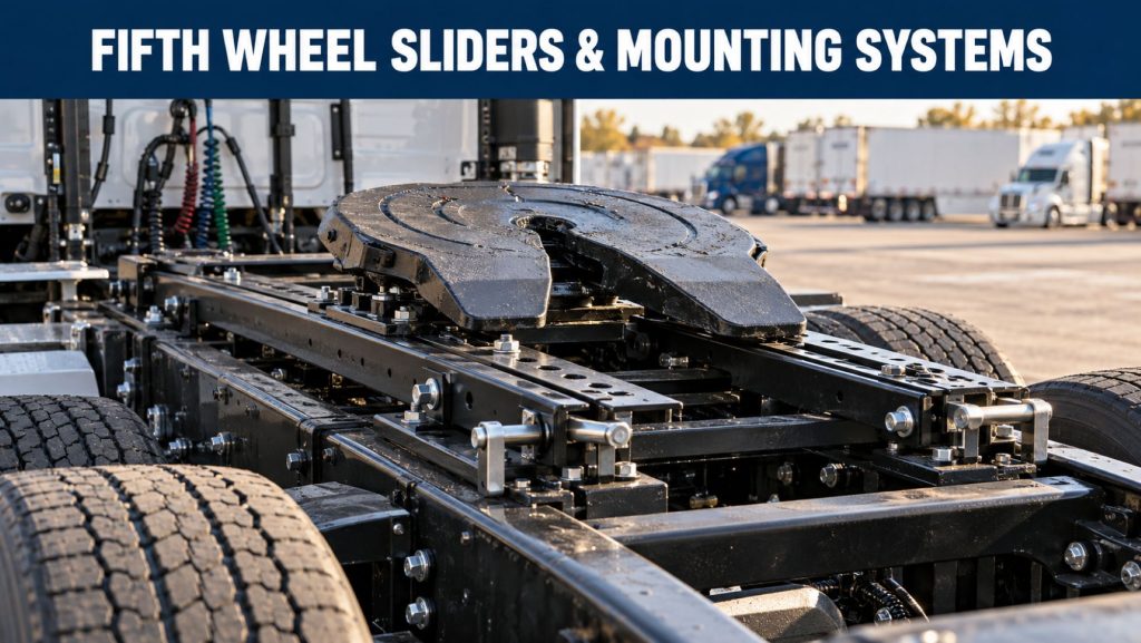
Fifth wheel sliders and mounting systems connect the fifth-wheel top plate to the tractor frame. These assemblies support the trailer’s vertical load, transfer pulling and braking forces into the chassis, and position the fifth wheel at the required height and location.
A sliding fifth-wheel system allows the fifth wheel to move forward or backward along rails mounted to the tractor frame. This adjustment changes the relationship between the trailer kingpin and the tractor axles, helping drivers and fleets manage steer-axle and drive-axle weight distribution.
Stationary mounting systems hold the fifth wheel in one fixed location. Other configurations include lightweight sliders, severe-duty sliders, oscillating mounts, no-tilt systems, air-operated releases, and application-specific mounting structures.
Fifth-Wheel Slider and Mounting Products on Truck Equipment Atlas
Individual fifth-wheel slider and mounting-system profiles are not yet available. The overview below explains these systems and their applications.
Additional slider rails, stationary mounts, lightweight systems, severe-duty assemblies, air-release mechanisms, locking components, mounting brackets, and replacement systems will be added as the Truck Equipment Atlas Fifth Wheels & Coupling Equipment Library continues to expand.
How Fifth-Wheel Slider Systems Work
A sliding fifth wheel is mounted on rails that run lengthwise along the tractor frame. Locking plungers, wedges, or another approved locking design secure the sliding assembly in one of several available positions.
When the locking mechanism is released, the tractor can move beneath the trailer while the trailer remains secured. This allows the fifth wheel to move forward or backward along the slider rails.
Once the desired position is reached, the locking mechanism must fully reengage. The driver must inspect the locking components on both sides of the slider before operating the vehicle.
Moving the fifth wheel forward generally transfers more trailer weight toward the tractor’s steer axle. Moving it rearward generally transfers weight away from the steer axle and toward the drive axles.
Major Slider and Mounting Components
A fifth-wheel slider and mounting assembly may include:
- Fifth-wheel top plate
- Mounting brackets
- Slider base
- Slider rails
- Positioning holes or notches
- Locking plungers or wedges
- Release linkage
- Manual release handle
- Air-release cylinder
- Air lines and fittings
- Pivot pins
- Bracket pins
- Bushings and liners
- Slider stops
- Frame brackets
- Crossmembers
- Mounting angles
- Structural fasteners
The exact component arrangement depends on the manufacturer, fifth-wheel model, mounting height, slide length, frame configuration, capacity, and application.
Slider Rails and Positioning
Slider rails guide the fifth wheel as it moves along the tractor frame. Holes, slots, or notches in the rails provide defined locking positions.
The amount of available slide travel depends on the mounting system. A longer slider can provide greater positioning flexibility but may add weight and require more available frame space.
Slider rails should remain straight, securely attached, and free from cracks, severe corrosion, damaged locking positions, and debris that could interfere with movement.
Locking Plungers and Wedges
Locking plungers or wedges prevent the fifth wheel from moving after the slider has been positioned. Depending on the design, the assembly may use two or more locking points.
All locking components must engage completely before road operation. A partially engaged plunger may allow unexpected fifth-wheel movement during acceleration, braking, cornering, or trailer loading.
Drivers should visually inspect both sides of the slider because one locking component may appear engaged while another remains partially released.
Manual Slider Release Systems
A manual slider uses a release handle, linkage, or lever to retract the locking components. The driver normally applies the trailer brakes, releases the slider locks, and carefully moves the tractor to reposition the fifth wheel.
Manual systems can be mechanically straightforward but may require the driver to leave the cab and reach near or beneath the trailer.
A release handle that moves normally does not guarantee that every locking component has disengaged or reengaged. Visual inspection remains necessary.
Air-Release Slider Systems
Air-release slider systems use compressed air to operate a cylinder connected to the locking mechanism. A control inside the cab or at another protected location commands the cylinder to retract or engage the slider locks.
An air-release system may include:
- Protected control switch
- Air cylinder
- Release linkage
- Air lines and fittings
- Control valve
- Return springs
- Safety interlocks
- Position or warning indicators
Air operation can make frequent slider adjustment easier, but it does not replace visual inspection. The driver must confirm that every locking component has fully engaged.
Stationary Fifth-Wheel Mounts
A stationary mount holds the fifth wheel in one permanent position on the tractor frame. It does not provide normal forward or rearward adjustment.
Stationary mounts may be appropriate when the tractor operates with consistent trailer types, kingpin settings, loads, axle positions, and weight-distribution requirements.
Potential advantages include lower weight, fewer moving components, reduced maintenance complexity, and a consistent fifth-wheel position.
The mounting position must be selected carefully because axle-weight adjustment cannot be made by sliding the fifth wheel.
Inboard and Outboard Mounting
Fifth-wheel mounting systems may use inboard or outboard mounting arrangements, depending on the tractor frame and assembly design.
Inboard mounts position mounting components closer to the inside of the frame rails. Outboard mounts use brackets or angles positioned along the outside of the frame rails.
The correct design depends on frame width, rail thickness, crossmember placement, mounting instructions, available space, and the forces created by the intended application.
Fifth-Wheel Mounting Height
Mounting height affects the position of the fifth-wheel top plate above the tractor frame. The selected height must provide correct trailer ride height and adequate clearance.
Mounting height can affect:
- Overall trailer height
- Trailer frame angle
- Tractor-to-trailer clearance
- Drive-tire clearance
- Landing-gear clearance
- Trailer rear clearance
- Suspension movement
- Aerodynamic alignment
A mounting system should not be selected solely because its fifth-wheel top plate fits the tractor. Height, frame compatibility, capacity, slider travel, and trailer clearance must all be confirmed.
Slide Length and Adjustment Range
Slide length describes the available forward and rearward travel of the fifth-wheel assembly. Systems may be offered with different rail lengths and adjustment increments.
The required travel depends on the tractor wheelbase, frame space, trailer kingpin location, axle-weight requirements, cab clearance, and typical load configurations.
A slider should never be positioned beyond its approved locking range or operated against damaged end stops.
Weight Distribution and Axle Loading
Changing the fifth-wheel position changes how trailer weight is distributed between the tractor’s steer and drive axles.
Moving the fifth wheel forward generally increases the load carried by the steer axle and reduces part of the load carried by the drive axles. Moving the fifth wheel rearward generally produces the opposite effect.
The actual weight transfer depends on:
- Tractor wheelbase
- Drive-axle position and spacing
- Fifth-wheel slide distance
- Trailer kingpin position
- Trailer axle position
- Cargo placement
- Fuel load
- Mounted tractor equipment
- Complete vehicle geometry
Certified scales should be used to confirm axle weights after the fifth wheel or cargo position has been changed.
Lightweight Slider Systems
Lightweight slider systems are designed to reduce tractor weight while retaining the adjustment capability required for axle-weight management.
Weight reduction may be achieved through optimized rail designs, fabricated brackets, modular construction, lightweight materials, and application-specific component sizing.
A lighter slider may help preserve payload capacity, but it must still meet the required vertical-load, pull, frame, and duty-cycle ratings.
Severe-Duty Slider Systems
Severe-duty sliders are designed for demanding vocational, heavy-haul, construction, logging, mining, oilfield, and off-highway applications.
These systems may use heavier rails, reinforced brackets, stronger locking mechanisms, increased structural capacity, additional frame support, and components designed for frequent shock and twisting loads.
A severe-duty slider adds weight and may require more chassis space, but it can provide the strength needed for applications beyond normal highway service.
Oscillating and Kompensator Mounting Systems
Oscillating and compensating mounting systems allow additional side-to-side fifth-wheel movement. This can reduce twisting forces transferred between the tractor and trailer while operating on uneven terrain.
These systems may be used in construction, logging, mining, oilfield, heavy-haul, and other specialized applications where the tractor and trailer frequently operate on uneven surfaces.
Additional articulation must be matched to the trailer, fifth wheel, mounting system, frame, load, and operating environment.
No-Tilt Mounting Systems
A no-tilt mounting system restricts or eliminates normal fifth-wheel tilting. It may be used in specialized applications where the trailer design requires a rigid or controlled mounting relationship.
No-tilt systems are not interchangeable with ordinary articulating fifth-wheel mounts. The complete tractor, trailer, frame, coupling, and operating application must be approved for the configuration.
Frame and Chassis Compatibility
The slider or stationary mounting system must match the tractor’s frame dimensions, rail strength, crossmember arrangement, suspension, axle position, and intended loading.
Compatibility depends on:
- Tractor manufacturer and model
- Model year and VIN
- Frame width and rail thickness
- Frame reinforcement
- Crossmember locations
- Drive-axle position
- Suspension configuration
- Available frame space
- Fuel tanks and battery boxes
- Exhaust and emissions equipment
- Hydraulic or vocational equipment
- Required fifth-wheel height
Frame drilling, welding, reinforcement, and fastener installation should follow approved engineering and manufacturer procedures.
Repositioning a Sliding Fifth Wheel
The exact repositioning procedure depends on the tractor and slider design. Drivers should follow the vehicle and fifth-wheel manufacturers’ instructions.
A typical procedure may include:
- Park on a firm, level surface whenever possible.
- Keep the tractor and trailer aligned.
- Apply the trailer brakes.
- Release the slider locking mechanism.
- Move the tractor slowly to reposition the fifth wheel.
- Stop at the desired rail position.
- Reengage the locking mechanism.
- Move the tractor slightly if needed to seat the locks.
- Visually inspect every locking plunger or wedge.
- Confirm clearance and axle weights before normal operation.
Highway Applications
Highway tractors commonly use sliding fifth wheels to accommodate different trailers, cargo arrangements, kingpin settings, and axle-weight requirements.
Important highway considerations include weight, corrosion resistance, slide travel, ease of adjustment, locking reliability, mounting height, parts availability, inspection access, and maintenance requirements.
Vocational and Heavy-Haul Applications
Vocational and heavy-haul applications can expose mounting systems to greater vertical, pulling, braking, twisting, and shock loads.
Common applications include:
- Dump trailers
- Lowboy and RGN trailers
- Logging trailers
- Oilfield equipment
- Mining equipment
- Tank trailers
- Construction equipment
- Specialized heavy-haul combinations
- Off-highway tractors
These applications may require severe-duty sliders, stationary mounts, oscillating systems, no-tilt configurations, higher capacities, frame reinforcement, or application-specific mounting structures.
Advantages of Sliding Fifth-Wheel Systems
- Adjustable fifth-wheel position
- Improved axle-weight management
- Compatibility with different trailer configurations
- Manual and air-release options
- Multiple slide lengths and mounting heights
- Lightweight and severe-duty configurations
- Replaceable locking and wear components
- Application-specific mounting options
The actual benefits depend on correct selection, installation, adjustment, inspection, maintenance, and vehicle loading.
Limitations and Considerations
- More weight than many stationary mounts
- Additional moving and wear components
- Potential locking-plunger problems
- Rail corrosion or contamination
- Air-cylinder and line failures
- Incorrect fifth-wheel positioning
- Incomplete lock engagement
- Reduced frame space
- Mounting-height and clearance requirements
- Frame compatibility limitations
- Increased inspection and maintenance requirements
A slider should never be operated with damaged rails, loose mounting components, or locking plungers that do not engage completely.
Driver and Operator Considerations
Drivers should understand how the slider is released, repositioned, locked, and inspected.
Important operating considerations include:
- Using firm and level ground when possible
- Keeping the tractor and trailer aligned
- Applying the correct brakes before adjustment
- Moving the tractor slowly
- Inspecting both sides of the slider
- Confirming complete lock engagement
- Checking tractor-to-trailer clearance
- Confirming legal axle weights on a scale
- Reporting difficult movement or release
Maintenance and Ownership
Fifth-wheel sliders and mounting systems require regular inspection and preventive maintenance.
Important maintenance areas can include:
- Slider rails and locking positions
- Locking plungers or wedges
- Release handles and linkage
- Air cylinders, lines, and fittings
- Return springs
- Mounting brackets and angles
- Pivot and bracket pins
- Bushings and liners
- Crossmembers
- Structural fasteners
- Tractor frame condition
- Lubrication points
- Corrosion protection
Maintenance requirements vary according to the manufacturer, slider model, load, duty cycle, operating environment, adjustment frequency, and frame installation.
Common Slider and Mounting Problems
Slider will not move: Loaded locking components, corrosion, damaged rails, debris, insufficient lubrication, frame distortion, or an air-cylinder failure may prevent movement.
Locks will not release: Air-system failure, damaged linkage, binding plungers, pressure against the locks, contamination, or corrosion may prevent release.
Locks will not engage: Rail misalignment, damaged plungers, worn locking positions, weak return springs, air-pressure problems, or incomplete tractor movement may prevent engagement.
Excessive slider movement: Worn rails, locking components, bushings, brackets, or mounting hardware may allow unwanted movement.
Air leaks: Damaged air lines, fittings, cylinders, seals, or control valves can prevent normal release operation.
Structural cracking: Overloading, corrosion, loose fasteners, collision damage, improper mounting, or unauthorized welding may damage the slider, brackets, or tractor frame.
Choosing a Fifth-Wheel Slider or Mounting System
Selecting a slider or mounting system requires identifying the complete tractor, fifth wheel, trailer, load, and operating application.
Important factors include:
- Tractor manufacturer, model, model year, and VIN
- Frame width, thickness, and strength
- Fifth-wheel manufacturer and model
- Vertical-load and pull ratings
- Required mounting height
- Required slide travel
- Manual or air release
- Inboard or outboard mounting
- Stationary or sliding configuration
- Highway, vocational, or severe-duty operation
- Oscillating or no-tilt requirements
- Tractor-to-trailer clearance
- Axle-weight adjustment requirements
- Available frame space
- Replacement-parts and service availability
A mounting system should not be selected only because it appears physically similar to the original assembly. Capacity, dimensions, locking design, mounting height, frame compatibility, and intended service must all be verified.
Related Fifth-Wheel and Coupling Categories
- Commercial Truck Fifth Wheels
- Fifth Wheel Sliders & Mounting Systems
- Kingpins and Upper Couplers
- Pintle Hooks and Drawbar Couplings
Related Fifth-Wheel Guides
- Fifth-Wheel Systems Explained
- Fixed vs Sliding Fifth Wheels
- How to Couple and Uncouple a Semitrailer
- How to Inspect and Maintain a Commercial Fifth Wheel
- Fixed vs Sliding Fifth Wheels
- Fifth Wheels & Coupling Equipment
Related Truck Equipment Resources
- Commercial Trucks
- Commercial Trailers
- Axles & Differentials
- Suspension Systems
- Brake Systems
- Tires & Wheels
- Equipment Systems
Understanding how the fifth wheel, slider rails, locking components, mounting brackets, tractor frame, suspension, axles, trailer kingpin, cargo placement, and axle weights work together is essential when evaluating a fifth-wheel mounting system.
Explore the Complete Fifth Wheels & Coupling Equipment Library
Fifth-wheel sliders and mounting systems represent one part of the larger tractor-and-trailer coupling-equipment category.
Visit the Fifth Wheels & Coupling Equipment Library to explore commercial fifth wheels, slider systems, stationary mounts, kingpins, upper couplers, pintle hooks, drawbar couplings, individual product profiles, and educational guides.
Additional sliders, mounting brackets, locking systems, air-release components, severe-duty systems, stationary mounts, manufacturers, replacement components, and educational resources will be added as Truck Equipment Atlas continues to expand.