
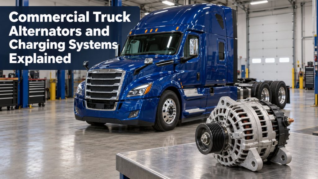
Commercial truck alternators and charging systems produce the electrical power needed to operate vehicle systems while the engine is running and restore energy removed from the batteries during starting. Modern trucks may depend on the charging system for engine and transmission controls, safety equipment, lighting, climate control, telematics, sleeper accessories, liftgates, refrigeration equipment, and many other electrical loads.
A charging system must do more than show an acceptable voltage at the alternator. The alternator, voltage regulator, drive system, batteries, cables, grounds, protection devices, sensors, and vehicle controls must work together. This guide explains how commercial truck alternators operate, the main alternator types, important ratings, charging-system components, common problems, testing methods, and application considerations.
What a Commercial Truck Charging System Does
When the engine is off, the batteries supply electrical power. During starting, they deliver high current to the starter motor. Once the engine begins running, the alternator converts mechanical energy from the engine into electrical energy. This power supports active vehicle loads and recharges the batteries.
The charging system must maintain voltage within a range that allows equipment to operate correctly without damaging batteries or electronic components. Output must adjust as engine speed, battery condition, temperature, and electrical demand change. For an overview of how charging fits into the complete vehicle network, see How Commercial Truck Electrical Systems Work.
How a Commercial Truck Alternator Works
An alternator uses electromagnetic induction to generate electricity. The engine turns the alternator pulley through a belt or gear drive. Inside the alternator, a rotating magnetic field called the rotor turns within stationary windings called the stator. This movement induces alternating current in the stator windings.
Because most truck electrical systems use direct current, a rectifier assembly containing diodes converts the stator’s alternating current into direct current. A voltage regulator controls the rotor’s field current so alternator output can increase or decrease as operating conditions change.
Alternator speed changes with engine speed, but electrical demand does not always follow the same pattern. A refuse truck, utility vehicle, or sleeper tractor may have high electrical demand at idle. The alternator must therefore be selected for useful output across the truck’s actual operating-speed range, not only its maximum advertised amperage.
Major Alternator Components
Rotor
The rotor creates the rotating magnetic field. In many alternators, electrical current reaches the rotor winding through brushes and slip rings. The strength of the rotor field affects how much electrical output the alternator can produce.
Stator
The stator contains stationary windings surrounding the rotor. As the magnetic field rotates, alternating current is induced in these windings. Stator design influences output, efficiency, heat generation, and low-speed performance.
Rectifier and Diodes
The rectifier converts alternating current into direct current. Diodes permit current to flow in one direction. A failed diode can reduce alternator output, introduce excessive alternating-current ripple, create electrical noise, or allow unwanted battery discharge.
Voltage Regulator
The voltage regulator monitors system conditions and adjusts field current to control alternator output. Regulators may be mounted inside the alternator, externally, or integrated with electronic vehicle controls. Some systems use battery temperature, remote voltage sensing, engine operating data, or network commands to refine charging behavior.
Bearings, Pulley, and Cooling Fan
Bearings support the rotor and allow it to turn at high speed. The pulley transfers engine power to the alternator, while the fan moves cooling air through or around the housing. Contamination, incorrect belt tension, misalignment, vibration, and normal wear can cause noise, heat, looseness, or seizure.
Brushes and Slip Rings
In a brushed alternator, carbon brushes contact slip rings to supply field current to the rotating rotor. Brushes and slip rings wear over time. Brushless heavy-duty alternators use a different excitation arrangement that eliminates these wearing contacts.
Common Commercial Truck Alternator Types
| Alternator Type | How It Works | Common Considerations |
|---|---|---|
| Brushed alternator | Brushes and slip rings deliver field current to the rotor | Widely used and serviceable, but brushes and slip rings wear |
| Brushless alternator | An internal excitation system supplies the rotating field without conventional brushes | Reduced brush maintenance and useful durability in high-mileage or severe service |
| Internally regulated alternator | The voltage regulator is built into the alternator | Compact installation and common on modern trucks |
| Externally regulated alternator | A separate regulator controls alternator field current | Found on some older, specialized, or multi-alternator systems |
| Remote-sense alternator | The regulator senses voltage closer to the batteries or distribution point | Helps compensate for cable voltage drop when installed correctly |
| High-output alternator | Designed to produce greater current for demanding electrical loads | Requires correct drive capacity, cooling, wiring, protection, and battery compatibility |
Understanding Alternator Ratings
Rated Amperage
An alternator’s amperage rating identifies its electrical current capability under specified test conditions. The maximum rating does not mean the alternator continuously produces that amount. Actual output depends on alternator speed, temperature, regulator command, battery state of charge, and connected loads.
Idle Output
Idle output is critical for trucks that operate lights, HVAC equipment, warning systems, hydraulic controls, liftgates, refrigeration accessories, or sleeper loads while the engine runs slowly. Two alternators with the same maximum rating may deliver very different current at idle.
Voltage Rating
The alternator must match the vehicle’s nominal electrical-system voltage. Most North American heavy trucks use 12-volt systems, while some specialized equipment uses 24 volts or multiple voltage systems. Installing an incompatible alternator can damage batteries, controls, lighting, and other equipment.
Temperature and Output Curves
Alternator output and durability are affected by temperature. Electrical resistance rises as windings heat, and electronic components must dissipate significant heat under high load. An output curve shows available current across a range of alternator speeds. Heavy-duty ratings should be compared using similar test conditions because a cold peak-output number may not represent sustained hot performance.
The Role of the Voltage Regulator
The regulator changes alternator field strength to maintain suitable system voltage. When electrical demand increases or battery voltage falls, it can increase field current and alternator output. When demand decreases or voltage rises, it reduces output.
The correct target voltage is not one fixed number for every truck. Battery chemistry, temperature, operating condition, and manufacturer strategy influence the commanded voltage. Some modern systems intentionally vary charging voltage to improve battery life, fuel efficiency, or energy management. A reading that differs from an older truck’s familiar value is not automatically a failure.
Remote Voltage Sensing
A standard regulator may respond to voltage measured inside or at the output terminal of the alternator. If resistance in the charging cables causes voltage loss, battery voltage can be lower than alternator voltage. A remote-sense circuit measures voltage at or near the battery or main distribution point so the regulator can compensate for normal cable loss.
A damaged or incorrectly connected sense wire can cause undercharging or overcharging. Remote sensing cannot safely compensate for severe corrosion, loose connections, undersized cables, or damaged grounds. Those problems must be repaired rather than hidden by higher alternator output.
How Batteries and Alternators Work Together
The alternator supplies electrical loads and replenishes the batteries, while the batteries provide starting power, stabilize voltage, and support temporary demand that exceeds alternator output. A weak or deeply discharged battery bank can keep the alternator operating at high output for an extended period, creating excessive heat and reducing alternator life.
An alternator is not intended to serve as a high-rate charger for batteries that are repeatedly allowed to become severely discharged. When appropriate, deeply discharged batteries should be charged and tested with suitable shop equipment before charging-system diagnosis. Battery construction and condition are covered in Commercial Truck Batteries Explained.
Charging Cables, Grounds, and Circuit Protection
Alternator output travels through heavy cables, terminals, switches, distribution points, protective devices, and battery connections. The return path may use dedicated cables, engine connections, frame grounds, or a combination of these. Resistance in either side of the circuit reduces charging performance and produces heat.
A loose terminal or corroded connection may allow a normal voltage reading when little current is flowing but create a large voltage drop under load. That is why voltage-drop testing should be performed while the charging system is operating under meaningful demand. Cable inspection, connector protection, and grounding practices are covered in How to Inspect and Maintain Truck Wiring and Electrical Connections.
Belt-Driven Alternator Systems
Many truck alternators are driven by a serpentine belt or dedicated V-belt. Correct belt tension and pulley alignment are essential. A loose or glazed belt can slip under high electrical load, reducing output and generating heat. Excessive tension can overload alternator bearings and other accessory-drive components.
The tensioner, idler pulleys, crankshaft pulley, alternator pulley, belt routing, and mounting brackets should be inspected together. Rubber dust, polished pulley surfaces, chirping, squealing, belt tracking problems, or repeated belt failure can indicate misalignment, incorrect tension, pulley wear, or a seized component.
High-Output and Severe-Service Charging Systems
Vocational trucks, refrigerated vehicles, wreckers, utility trucks, refuse trucks, buses, and sleeper tractors may require more output than a standard charging system provides. High-output alternators can support greater demand, but upgrading the alternator alone may not be sufficient.
- Drive belts and pulleys must transmit the additional mechanical load.
- Output and ground cables must carry the available current safely.
- Connections and protection devices must have suitable ratings.
- Battery capacity and construction must match the duty cycle.
- Cooling airflow must be adequate for sustained high output.
- Idle-speed output must meet the loads used during actual operation.
- Engine controls may need to support idle-up or load-management functions.
Some applications use dual alternators for additional capacity, redundancy, or separate electrical systems. These installations require approved mounting, drive, regulation, wiring, and load-sharing arrangements.
Smart Charging and Load Management
Modern commercial vehicles may connect the alternator, engine controller, body controller, battery sensors, and electrical-load controls through a data network. The system can adjust charging based on battery state, temperature, engine load, operating mode, and equipment demand.
Load-management systems may shed nonessential equipment when voltage becomes low or total demand exceeds available output. Idle-up controls may increase engine speed so the alternator can support high stationary loads. Diagnosis may therefore require fault-code information, network data, and manufacturer procedures in addition to traditional meter tests.
Common Charging-System Problems
| Symptom | Possible Causes |
|---|---|
| Low charging voltage | Loose belt, weak alternator, high cable resistance, poor ground, damaged sense circuit, heavy load, discharged batteries, or regulator fault |
| High charging voltage | Regulator fault, open or incorrect sense circuit, poor battery connection, wiring problem, or incompatible alternator |
| Battery warning light | Low or high voltage, loss of alternator output, belt problem, wiring fault, communication fault, or controller-detected condition |
| Intermittent output | Loose connection, worn brushes, damaged wiring, failing regulator, heat-related internal fault, or belt slip |
| Alternator noise | Worn bearing, pulley problem, belt misalignment, loose mounting, internal contact, or diode-related electrical hum |
| Repeated alternator failure | Overloaded alternator, discharged batteries, poor cooling, cable resistance, incorrect belt tension, contamination, vibration, or wrong replacement unit |
| Electrical noise or unusual ripple | Failed diode, stator problem, poor ground, loose connection, or internal alternator fault |
| Hot cables or terminals | Loose connection, corrosion, undersized cable, excessive current, damaged lug, or poor crimp |
How a Commercial Truck Charging System Is Tested
- Confirm the complaint. Note warning lights, gauge readings, starting behavior, battery condition, recent repairs, and the loads operating when the problem occurs.
- Inspect the system. Check the alternator, mounts, belt, tensioner, pulleys, cables, terminals, grounds, protection devices, and remote-sense wiring.
- Test the batteries. A defective or discharged battery bank can distort charging results and overload the alternator.
- Measure voltage before starting. Battery state of charge affects the output the alternator will be asked to provide.
- Measure charging voltage. Compare readings at the alternator and batteries under the conditions specified by the manufacturer.
- Apply electrical load. Operate approved loads or use proper test equipment while monitoring voltage and current.
- Measure alternator current. Determine whether output responds to battery condition and system demand.
- Perform voltage-drop tests. Test both the positive and negative sides of the charging circuit while current is flowing.
- Check alternating-current ripple. Excessive ripple can indicate failed diodes or stator problems.
- Review electronic data. On controlled systems, inspect fault codes, commanded voltage, field duty cycle, battery sensor data, and load-management status.
A single voltage measurement does not identify every charging problem. Testing should account for battery condition, temperature, engine speed, electrical load, and the manufacturer’s charging strategy.
Voltage-Drop Testing
Voltage-drop testing measures the voltage lost across cables, connections, switches, and grounds while current is flowing. To test the positive side, a meter is connected between the alternator output and battery positive point. To test the negative side, the meter is connected between the alternator housing or specified ground point and battery negative.
The acceptable reading depends on the vehicle and circuit design. A high reading means unwanted resistance exists somewhere between the test points. Dividing the circuit into smaller sections can locate the problem. Do not condemn an alternator solely because battery voltage is low until cable and ground losses have been evaluated.
Alternating-Current Ripple Testing
The rectifier should convert alternator output into relatively smooth direct current. A failed diode or stator winding can allow excessive alternating-current ripple into the electrical system. Symptoms may include reduced output, battery discharge, electronic interference, lamp flicker, unusual noise, communication faults, or premature component failure.
Ripple can be measured with an appropriate meter or viewed with an oscilloscope. Test method and acceptable values vary, so the correct service information should be used.
Charging-System Inspection and Maintenance
- Keep batteries fully charged and test weak units promptly.
- Inspect alternator mounts and fasteners for looseness, cracks, or movement.
- Maintain correct belt condition, alignment, and tension.
- Keep cooling openings clear of oil, dirt, and debris.
- Inspect output cables, sense wires, connectors, and grounds for corrosion or heat damage.
- Protect cables from exhaust heat, sharp edges, abrasion, and moving parts.
- Use correct terminal torque and protective covers.
- Investigate warning lamps, unusual voltage, noise, or repeated battery discharge early.
- Test for parasitic draw when batteries discharge while the truck is parked.
- Follow manufacturer procedures before disconnecting batteries or welding on the vehicle.
Lighting circuits can represent a substantial continuous load, particularly on trucks and trailers with numerous lamps or work lights. The guide to Commercial Truck and Trailer Lighting Systems Explained covers those loads and their supporting circuits.
Selecting a Replacement Alternator
A replacement alternator must match more than the advertised amperage. Mounting configuration, electrical-system voltage, pulley type and diameter, rotation, connector arrangement, regulator strategy, remote-sense requirements, communication capability, output curve, environmental rating, and terminal location may all matter.
The unit should provide adequate hot output at the engine speeds where the truck actually operates. Oversizing without evaluating belts, cables, protection, batteries, and cooling can create new problems. Undersizing can leave the batteries chronically undercharged and keep the alternator near maximum output.
How Starting-System Problems Affect Charging
A starter that draws excessive current removes more energy from the batteries and increases the charging work required after each start. Long cranking caused by fuel, engine, control, cable, or starter problems can produce the same effect. Repeatedly correcting discharged batteries without addressing the starting fault can shorten both battery and alternator life.
The relationship between cranking current, starter condition, controls, cables, and batteries is explained in Commercial Truck Starters and Starting Systems Explained.
Frequently Asked Questions
How many amps should a truck alternator produce?
There is no single correct output for every truck. Required capacity depends on the vehicle’s electrical loads, battery bank, operating speed, duty cycle, temperature, and manufacturer specifications. Actual output also changes according to demand.
Does the alternator charge at idle?
Yes, but available current at idle may be much lower than the alternator’s maximum rating. If connected loads exceed idle output, the batteries may supply the difference even though the engine is running.
Can a bad battery damage an alternator?
A defective or deeply discharged battery can keep the alternator at high output, increasing heat and stress. An internal battery problem can also affect voltage regulation or create unusual current demand.
Why is alternator voltage normal but the batteries remain low?
Possible causes include resistance in output cables, grounds, switches, or connections; an incorrect remote-sense circuit; excessive electrical load; damaged batteries; or insufficient charging time. Compare voltage at the alternator and batteries while current is flowing.
Can a larger alternator be installed without other changes?
Not always. Higher output may require different cables, protection devices, belts, pulleys, mounting hardware, cooling, batteries, programming, or load-management controls. The complete system should be evaluated before an upgrade.
The Role of the Charging System in Truck Reliability
The alternator and charging system support nearly every electrical function on a modern commercial truck. Reliable operation depends on correct alternator capacity, healthy batteries, low-resistance cables and grounds, a sound drive system, effective cooling, and regulation matched to the vehicle.
Testing the system under realistic speed and load conditions is more effective than replacing components based on one voltage reading. Early correction of belt wear, cable resistance, battery problems, overloaded circuits, and warning indicators helps reduce no-start events, electronic faults, roadside downtime, and repeated component failure.