
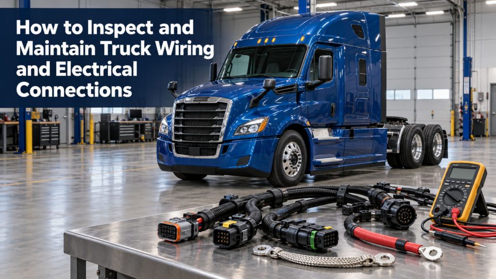
Commercial truck wiring and electrical connections operate in an environment filled with vibration, heat, moisture, road salt, oil, dirt, and constant movement. A small amount of corrosion, a loose ground, or damaged insulation can interrupt starting, charging, lighting, electronic controls, trailer functions, and auxiliary equipment.
Effective electrical maintenance combines careful visual inspection with testing performed while the circuit is operating. This guide explains how to inspect wiring harnesses, battery cables, connectors, grounds, terminals, circuit protection, and truck-to-trailer connections; how to recognize common problems; and how to perform maintenance without creating additional damage.
Why Truck Wiring and Connection Maintenance Matters
Electrical current must travel through a complete circuit from the power source, through the load, and back to the source. Resistance at a connector, terminal, splice, cable, or ground reduces the voltage available to the component and converts electrical energy into heat.
Low-current sensor circuits can be disrupted by a small change in resistance, while starter and charging circuits can generate intense heat at a poor connection because they carry high current. Reliable electrical operation therefore depends on clean contact surfaces, secure terminals, correct wire size, sound insulation, proper routing, and dependable grounds. The guide How Commercial Truck Electrical Systems Work explains how these paths connect the major systems.
Common Types of Truck Wiring and Connections
Battery Cables
Battery cables carry high current between the battery bank, starter, alternator, disconnect switches, and grounding points. They use large conductors and heavy lugs. Internal corrosion, damaged strands, loose crimps, or poor terminal contact can cause starting and charging problems even when the cable looks acceptable from the outside.
Wiring Harnesses
Harnesses group multiple wires and circuits into protected assemblies. Loom, tape, conduit, clips, brackets, and grommets protect the wires and maintain routing. Harnesses may serve the engine, chassis, cab, body, lighting, transmission, brakes, trailer, or auxiliary equipment.
Sealed Electrical Connectors
Sealed connectors use gaskets, terminal seals, locks, and secondary retainers to limit contamination and keep terminals aligned. A connector is only sealed when its housing, seals, plugs, locks, and wire entries are intact and correctly assembled.
Ring Terminals and Stud Connections
Ring terminals are common at batteries, starters, alternators, grounds, junction studs, circuit breakers, and power-distribution points. Correct surface preparation, hardware order, terminal size, torque, support, and protection are essential.
Splices
Factory splices divide or join circuits within a harness. Service repairs may use approved crimp splices, sealed connectors, or manufacturer-specified repair terminals. An unsealed or poorly supported splice can become a point of corrosion, resistance, or wire breakage.
Ground Connections
Ground paths return current to the battery negative side. Trucks may use dedicated ground wires, engine grounds, frame grounds, cab grounds, and bonding straps. Paint, rust, corrosion, loose hardware, broken straps, or movement between vehicle structures can increase ground resistance.
Truck-to-Trailer Connectors
The tractor electrical receptacle, trailer plug, seven-way cable, junction box, and trailer harness carry lighting, brake, auxiliary, and communication circuits. These connections face repeated coupling, pulling, flexing, weather exposure, road spray, and accidental strain.
Safety Before Electrical Inspection
Truck electrical systems can produce dangerous heat, arcing, battery gas, and unexpected equipment movement. Before inspection or repair, secure the vehicle, follow lockout and isolation procedures, wear appropriate eye and hand protection, and use insulated tools where required.
- Follow the vehicle manufacturer’s battery-disconnection procedure.
- Protect electronic settings and modules as specified before removing power.
- Never place tools across battery terminals or unprotected power studs.
- Do not probe insulation unnecessarily or create openings that admit moisture.
- Keep sparks and ignition sources away from batteries.
- Use proper support before working beneath a vehicle or raised cab.
- Disable moving equipment such as liftgates, dump bodies, fans, and hydraulic systems.
- Follow manufacturer instructions before welding on the truck or trailer.
A Complete Visual Inspection Process
- Review the complaint and history. Determine which systems fail, when the problem occurs, and whether recent repairs or equipment installations are related.
- Inspect the batteries and battery box. Check cases, hold-downs, terminals, interconnect cables, disconnect switches, grounds, covers, and drainage.
- Follow the main power cables. Inspect routes to the starter, alternator, power-distribution center, and auxiliary equipment.
- Inspect harness routing. Look for contact with exhaust parts, sharp edges, moving components, frame joints, suspension travel, and areas that collect debris.
- Check clips, clamps, and grommets. Missing supports allow vibration and abrasion to damage wires.
- Inspect connectors. Check housings, seals, locks, terminal position, wire entry, strain relief, contamination, and heat damage.
- Inspect grounds and bonding straps. Look for corrosion, loose hardware, broken strands, paint under terminals, and movement between grounded structures.
- Check circuit protection. Verify that fuses, circuit breakers, fusible links, and covers are correct and securely installed.
- Inspect truck-to-trailer wiring. Examine the plug, socket, cable, spring support, junction box, trailer harness, and lamp connections.
- Operate the system. Wiggle-test suspect areas carefully while monitoring the circuit, and reproduce the vehicle conditions associated with the complaint.
Signs of Wiring and Connection Problems
| Condition | What It May Indicate |
|---|---|
| Green or white corrosion | Moisture entry, acid exposure, damaged plating, or inadequate sealing |
| Darkened or melted connector | Loose terminal, excessive resistance, overload, poor crimp, or incorrect terminal fit |
| Stiff or swollen cable insulation | Heat, chemical exposure, internal corrosion, or age-related deterioration |
| Shiny or flattened harness covering | Rubbing against a bracket, frame, hose, or moving component |
| Repeatedly blown fuse | Short to ground, overloaded circuit, incorrect fuse, damaged component, or wiring fault |
| Intermittent operation over bumps | Loose terminal, broken conductor, poor ground, connector movement, or chafed harness |
| Multiple unrelated warning lights | Low system voltage, shared ground problem, network wiring fault, or power-distribution issue |
| Hot terminal or cable | High resistance, loose connection, undersized conductor, or excessive current |
| Moisture inside connector | Damaged seal, missing plug, poor routing, pressure washing, or incorrect assembly |
| Frequent lamp failure | Voltage problem, poor ground, vibration, water intrusion, connector damage, or incorrect lamp |
How to Inspect Battery Connections
Inspect each battery case, post, terminal, interconnect cable, hold-down, and nearby surface. Look for acid residue, corrosion, cracks, swelling, loose hardware, missing covers, overheated terminals, and movement within the battery box.
Connections should be cleaned and tightened according to the battery and vehicle manufacturers’ procedures. Overtightening can damage posts, terminals, or cases. A multi-battery bank should have balanced, correctly routed cables so individual batteries do not carry unequal portions of the starting or charging load.
Battery condition must be evaluated along with connection condition. A weak battery can imitate a cable problem, while a poor connection can make a healthy battery appear defective. Battery construction, ratings, and bank configuration are covered in Commercial Truck Batteries Explained.
How to Inspect Grounds and Bonding Straps
Grounds should be inspected at the batteries, engine, frame, cab, body, trailer, electrical modules, lamps, and auxiliary equipment. A connection can look tight while corrosion or paint between the terminal and mounting surface creates resistance.
Flexible bonding straps are used where the engine, cab, hood, body, or other structure moves relative to the frame. Check straps for broken strands, stiffness, corrosion, loose ends, and insufficient slack. Grounds should be restored using the approved surface preparation, hardware, torque, and corrosion protection.
How to Inspect Wiring Harnesses
Follow the harness rather than checking only the area near the failed component. Pay particular attention to bends, branch points, connectors, frame crossings, pass-throughs, hinges, suspension areas, and locations near heat or sharp metal.
- Look for missing clips, loose ties, and incorrect routing.
- Check loom and tape for abrasion, cuts, swelling, brittleness, or discoloration.
- Inspect grommets where wires pass through metal panels.
- Confirm that harnesses have enough movement without being stretched.
- Keep wiring separated from exhaust pipes, turbocharger components, and aftertreatment equipment.
- Inspect areas contaminated by fuel, oil, coolant, hydraulic fluid, or battery electrolyte.
- Check repaired areas for correct wire size, sealed splices, and adequate support.
- Look for non-factory accessories connected without proper protection or strain relief.
How to Inspect Electrical Connectors
Before disconnecting a connector, examine its position and routing. Confirm that the lock is engaged and the wires are not pulling on the rear of the housing. After disconnection, inspect the terminals, seals, cavities, locks, and mating surfaces using adequate light and magnification when necessary.
- Terminals should be straight, correctly positioned, and fully retained.
- Male and female terminals should not be spread, recessed, pushed out, or bent.
- Seals should be flexible, undamaged, and correctly seated.
- Unused cavities should contain the specified sealing plugs.
- There should be no water, dirt, oil, corrosion, or metal debris inside.
- The connector housing should not be cracked, melted, or distorted.
- Secondary locks and strain-relief features should be present and engaged.
Do not force test probes into terminal cavities. Oversized probes can spread terminals and create a new intermittent fault. Use the approved breakout leads, back-probing methods, or terminal adapters for the connector.
Cleaning and Protecting Electrical Connections
Cleaning methods must match the connector and type of contamination. Disconnect power when required. Use products approved for electrical service and compatible with terminal plating, plastics, rubber seals, and surrounding materials. Allow cleaned parts to dry before reconnection.
Dielectric grease may be specified for certain seals or connector interfaces, but it should not be applied indiscriminately. Too much grease can prevent full seating, attract contamination, or interfere with some terminal designs. Conductive compounds should only be used where specifically approved.
External terminals and grounds may require protective coatings after assembly. Protection should never be used to conceal an unclean or loose connection. The electrical contact surfaces must first be restored and secured correctly.
Voltage-Drop Testing
Voltage-drop testing is one of the most useful ways to find unwanted resistance. The circuit must be operating so current flows through the cable, terminal, switch, connector, or ground being tested. The meter measures the voltage lost between two points.
A high reading means excessive resistance exists within the tested section. Divide the circuit into smaller sections until the loss is isolated. Acceptable limits vary by circuit, current, length, and manufacturer specification.
High-current starter and alternator circuits should be tested under meaningful load. The starting guide explains cranking-circuit testing in Commercial Truck Starters and Starting Systems Explained, while charging-circuit diagnosis is covered in Commercial Truck Alternators and Charging Systems Explained.
Continuity and Resistance Testing
Continuity testing can identify an open conductor, but it does not prove that the circuit can carry its normal load. A nearly broken wire may pass a small meter current while failing when a motor, lamp, or solenoid operates.
Resistance measurements should generally be performed with power removed from the circuit. Connected modules, parallel paths, capacitors, and other components can affect readings or be damaged by incorrect testing. Follow the wiring diagram and manufacturer procedure before disconnecting electronic equipment.
Testing for Shorts to Ground or Power
A short to ground occurs when a powered conductor contacts ground before the intended load. A short to power occurs when voltage enters a circuit from another powered conductor. Either problem may be constant or appear only when a harness moves, becomes wet, heats up, or vibrates.
Use the wiring diagram to isolate branches and components systematically. Replace a blown fuse only with the correct rating. Installing a larger fuse can allow the wiring to overheat and may create a fire risk. Circuit-protection test tools should be used according to their instructions rather than repeatedly sacrificing fuses.
Inspecting Fuses, Circuit Breakers, and Power Distribution
Inspect fuse and relay centers for loose covers, water entry, corrosion, overheated terminals, incorrect devices, damaged seals, and evidence of unauthorized modifications. A fuse can appear intact but fail at its blades or socket, so voltage should be checked on both sides when the circuit is powered.
Relays should match the circuit’s terminal arrangement and rating. Swapping relays can assist diagnosis only when the units are genuinely identical and the procedure will not affect a safety-critical system. Loose relay or fuse sockets require proper terminal repair rather than bending parts for temporary contact.
Truck-to-Trailer Electrical Connection Maintenance
Inspect the tractor socket, trailer plug, cable, spring support, clamps, junction box, and trailer harness. The cable should have enough length for turns without dragging, stretching, or contacting the deck, frame, exhaust, or air lines.
- Check plug and socket housings for cracks and loose covers.
- Inspect pins and sockets for corrosion, spreading, burning, or contamination.
- Confirm that strain relief grips the cable jacket rather than individual wires.
- Check the cable for cuts, kinks, flattened areas, and internal conductor damage.
- Inspect junction-box seals, terminals, covers, and cable entries.
- Verify grounds between the tractor, trailer, and individual lamps.
- Operate every lighting and auxiliary circuit after service.
Trailer connection condition directly affects marker lamps, stop-turn-tail lamps, ABS power, and auxiliary circuits. See Commercial Truck and Trailer Lighting Systems Explained for complete lighting-system coverage.
Repairing Damaged Truck Wiring
A durable repair should restore conductor capacity, insulation, sealing, mechanical strength, flexibility, and routing. Use the correct wire gauge, insulation type, color or circuit identification, terminal, seal, crimp tool, and splice method.
Approved crimped and sealed repairs are commonly preferred in vehicle harnesses because they can tolerate vibration when correctly made and supported. Soldering may create a rigid section that concentrates flexing at the edge of the repair, and it should only be used where the manufacturer permits it.
- Remove enough damaged wire to reach clean, flexible conductor.
- Use replacement wire with the required gauge, temperature rating, and insulation.
- Strip insulation without nicking or cutting conductor strands.
- Use the specified terminal or sealed splice and the correct crimping tool.
- Verify conductor and insulation crimps where applicable.
- Seal the repair using the approved method.
- Stagger multiple splices so the harness does not become bulky or rigid.
- Restore loom, tape, conduit, clips, grommets, and routing.
- Test the repaired circuit under its normal load.
Common Electrical Maintenance Mistakes
- Replacing components before testing power and ground
- Checking continuity without load-testing the circuit
- Using oversized probes that damage connector terminals
- Piercing wire insulation and leaving the hole unsealed
- Installing a larger fuse to stop repeated fuse failure
- Using household connectors or wire not rated for vehicle service
- Leaving repaired wiring unsupported
- Routing harnesses against heat, sharp edges, or moving parts
- Applying excessive grease inside connectors
- Tightening terminals without holding the stud from rotating
- Ignoring shared grounds when several systems fail together
- Pressure washing directly into electrical connectors
Suggested Preventive Inspection Schedule
| Inspection Opportunity | Recommended Focus |
|---|---|
| Pre-trip or daily walkaround | Lighting operation, visible cable damage, loose trailer cord, warning lamps, and signs of overheating |
| Routine preventive maintenance | Batteries, cables, grounds, harness routing, clips, connectors, fuse centers, trailer connections, and accessory wiring |
| Seasonal inspection | Corrosion, weather seals, cold-start circuits, high-demand charging connections, and road-salt exposure |
| After collision or body repair | Pinched harnesses, missing grounds, damaged connectors, incorrect routing, and module communication |
| After accessory installation | Wire sizing, circuit protection, grounding, load capacity, routing, and battery or alternator demand |
| After repeated electrical fault | Full circuit testing under load rather than another temporary component replacement |
Frequently Asked Questions
Can a connection be bad even if it looks clean?
Yes. Corrosion can exist between contact surfaces or inside a cable, and a loose terminal may appear normal until current flows. Voltage-drop testing under load is often needed.
Should dielectric grease be placed on every connector?
No. Use it only where the connector or equipment manufacturer recommends it, and apply the specified amount. Connector design and terminal contact requirements vary.
Why do electrical problems appear after rain?
Water may enter a damaged connector, harness, junction box, lamp, or fuse center. Moisture can create leakage paths, corrosion, or temporary shorts. Inspect seals, routing, drains, covers, and pressure-wash exposure.
Why does a truck lose power over bumps?
A loose terminal, broken conductor, damaged ground, worn ignition connection, or chafed harness may open or short as the vehicle moves. A controlled wiggle test and circuit monitoring can help isolate the area.
Is an ohmmeter enough to test a battery cable?
No. A damaged cable may show low resistance with the circuit off but fail under starter or alternator current. Voltage-drop testing under load gives a better picture of actual cable performance.
The Role of Wiring Maintenance in Truck Reliability
Wiring and connections connect every electrical source, control, and load on a commercial truck and trailer. Small faults can produce no-start conditions, weak charging, lighting failures, false warning codes, intermittent controls, damaged modules, and roadside downtime.
Routine inspection, correct routing, secure grounds, sealed repairs, and testing under load help locate developing problems before they interrupt operation. Good electrical maintenance also protects batteries, starters, alternators, lights, safety systems, and auxiliary equipment from avoidable stress.