
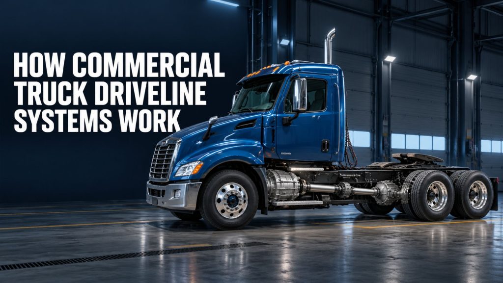
A commercial truck driveline transfers rotational power from the transmission to the drive axles. It must carry substantial torque while accommodating suspension movement, chassis flex, changing operating angles, and variations in the distance between drivetrain components.
The driveline may appear to be a simple collection of shafts and joints, but its geometry, balance, alignment, lubrication, and torque capacity are critical to the truck’s performance and reliability.
A problem with a driveshaft, universal joint, slip joint, carrier bearing, yoke, or driveline angle can produce vibration, noise, accelerated wear, or a sudden mechanical failure.
This guide explains how commercial truck driveline systems work, how power moves from the transmission to the drive axles, why universal joints and slip assemblies are necessary, and how driveline configurations differ among single-drive, tandem-drive, vocational, heavy-haul, and all-wheel-drive trucks.
What Is a Commercial Truck Driveline?
The driveline is the group of components that transfers rotational power between the transmission and the truck’s driven axles.
A conventional rear-wheel-drive commercial truck driveline can include:
- Transmission output yoke or flange
- Main driveshaft
- Universal joints
- Slip joint or slip spline
- Center or carrier bearing
- Intermediate driveshaft sections
- Axle input yoke or flange
- Inter-axle driveshaft on tandem-drive trucks
The exact design depends on the truck’s wheelbase, transmission, suspension, number of drive axles, ride height, frame configuration, and operating application.
Driveline, Drivetrain, and Powertrain
The terms driveline, drivetrain, and powertrain are sometimes used interchangeably, but they can describe different groups of components.
A simplified distinction is:
- Powertrain: The complete system that creates and transfers power, generally including the engine, transmission, driveline, and drive axles.
- Drivetrain: The components that transmit engine power to the wheels, commonly including the transmission, driveline, differentials, and drive axles.
- Driveline: The driveshafts, universal joints, slip assemblies, yokes, flanges, and supporting components between the transmission and driven axles.
Terminology can vary among manufacturers and service publications. The exact components being discussed should always be identified rather than relying on terminology alone.
The Commercial Truck Power Path
A conventional commercial truck power path can be simplified as:
Engine → Clutch or Torque Converter → Transmission → Driveshaft → Drive-Axle Differential → Axle Shafts → Wheels and Tires
The engine creates rotational power. The transmission provides different gear ratios. The driveline carries the resulting speed and torque to the drive axle.
The drive axle provides final-drive reduction, changes the direction of power flow, distributes torque to the axle shafts, and allows the drive wheels to rotate at different speeds during turns.
Every part of this system must be compatible with the truck’s engine torque, transmission gearing, axle ratio, tire size, vehicle weight, suspension, and duty cycle.
The Transmission Output Connection
Power enters the driveline through the transmission output shaft.
The output connection may use a:
- Full-round end yoke
- Half-round yoke
- Companion flange
- Specialized flange or coupling
The driveshaft connects to this output through a universal joint or compatible flange arrangement.
The output connection must carry both steady torque and changing loads created by acceleration, shifting, engine braking, road conditions, and equipment operation.
Main Driveshaft
The main driveshaft is the rotating shaft that carries power from the transmission toward the drive axle.
A commercial truck driveshaft generally includes a hollow tube with a yoke or flange arrangement at each end. The hollow construction provides strength while limiting rotating weight.
The driveshaft must be capable of handling:
- Engine torque
- Transmission torque multiplication
- Driveline speed
- Vehicle weight
- Shock loading
- Operating angle
- Vehicle duty cycle
- Maximum driveshaft length
A larger or heavier truck does not automatically use one particular driveshaft size. The correct shaft depends on the complete drivetrain and application.
Why Driveshafts Are Hollow
Most commercial truck driveshafts use hollow tubular construction rather than a solid shaft.
This arrangement provides an effective balance of:
- Torsional strength
- Bending stiffness
- Lower rotating weight
- Manufacturing efficiency
- Resistance to critical-speed problems
Tube diameter, wall thickness, material, shaft length, and joint series are selected according to the required torque and operating speed.
A driveshaft should never be replaced with tubing selected only by visual size. The complete assembly must meet the manufacturer’s application requirements.
Universal Joints
Universal joints, commonly called U-joints, allow a driveshaft to transmit power when the transmission and axle are not positioned in a perfectly straight line.
A conventional cross-type universal joint includes:
- Central cross or spider
- Four trunnions
- Bearing cups
- Needle bearings
- Seals
- Retaining hardware
Two bearing cups connect the joint to one yoke, while the other two connect it to the opposing yoke.
This arrangement allows the driveshaft to operate through an angle while continuing to transfer torque.
Why Universal Joints Are Necessary
The transmission is attached to the truck’s frame or powertrain mounts, while the drive axle moves with the suspension.
As the truck travels over bumps, carries different loads, accelerates, brakes, or experiences chassis movement, the vertical and longitudinal relationship between the transmission and axle changes.
Universal joints allow the driveline to continue transmitting power through these changing conditions.
Without flexible joints, normal suspension and chassis movement would place severe bending loads on the transmission, driveshaft, and axle input components.
Universal-Joint Operating Speed
A conventional universal joint operating at an angle does not transfer rotational speed perfectly uniformly throughout each revolution.
The driven side speeds up and slows down slightly as the joint rotates. A correctly designed driveline uses joint geometry and phasing to manage or cancel these speed variations.
If operating angles are excessive or incorrectly related, the speed variations can produce:
- Driveline vibration
- Noise
- Universal-joint wear
- Transmission output wear
- Axle input wear
- Carrier-bearing damage
- Reduced component life
Driveline Operating Angles
A driveline operating angle is the angle created where two connected shaft centerlines meet at a universal joint.
Important centerlines can include:
- Transmission output shaft
- Driveshaft
- Intermediate shaft
- Drive-axle pinion shaft
The correct angles depend on the driveline design and manufacturer specifications. The goal is not always to make every component perfectly level or place every joint at zero angle.
Some universal joints require a small operating angle to circulate lubricant through the bearings. Excessive angle, inadequate angle, or poorly matched angles can all create problems.
Ride height must be correct before driveline angles are measured. A suspension or chassis-height problem can change the measurements and create driveline vibration.
Driveshaft Phasing
Driveshaft phasing describes the rotational alignment of the yokes at opposite ends of a shaft.
On many conventional driveshafts, the yokes must remain aligned in a specific relationship so the speed variations created by one universal joint can be offset by the other.
If a slip assembly is separated and reassembled incorrectly, the driveshaft may be out of phase.
An out-of-phase driveshaft can create severe vibration even when the shaft is balanced and the universal joints are new.
Marking the shaft sections before disassembly and following the service manual during reassembly help preserve the required phasing.
Slip Joints and Slip Splines
A slip joint allows the effective length of the driveline to change.
As the suspension moves, the distance between the transmission and drive axle can increase or decrease. Chassis flex and powertrain movement can also change this distance.
The slip assembly commonly includes:
- Splined shaft
- Matching slip yoke or sleeve
- Seal
- Protective boot or shroud where used
- Lubrication provision on serviceable designs
The splines transfer torque while allowing controlled longitudinal movement.
A slip joint that binds can place damaging thrust loads on the transmission and axle. Excessive spline wear can create looseness, clunking, vibration, and changing driveline geometry.
Yokes and Flanges
Yokes and flanges connect the driveshaft to the transmission, axle, universal joints, and other driveline sections.
Common connection styles include:
- Full-round yokes
- Half-round yokes
- Wing-style yokes
- Companion flanges
- End yokes
- Slip yokes
- Weld yokes
The connection style affects assembly, retaining hardware, service procedures, joint installation, and torque requirements.
Yokes should be inspected for cracks, spreading, damaged bores, worn locating surfaces, loose fasteners, and other deformation.
Single-Piece Driveshafts
A single-piece driveline uses one main driveshaft between the transmission and drive axle.
This configuration can reduce the number of universal joints, carrier bearings, and mounting brackets required.
However, the shaft’s length, diameter, torque capacity, and critical speed must remain suitable for the truck.
Single-piece shafts are more practical when the distance between the transmission and axle can be covered safely by one correctly engineered assembly.
Multi-Piece Drivelines
Long-wheelbase trucks often use two or more driveshaft sections.
Dividing the driveline into shorter sections can help manage driveshaft length, operating angles, packaging, and critical speed.
A multi-piece driveline can include:
- Front or coupling shaft
- Center bearing
- Rear driveshaft
- Multiple universal joints
- One or more slip assemblies
Each additional joint and support introduces another component that must be correctly positioned, aligned, lubricated, and maintained.
Center and Carrier Bearings
A center bearing, also commonly called a carrier bearing, supports an intermediate driveshaft section in a multi-piece driveline.
The assembly commonly includes:
- Bearing
- Rubber or elastomer support
- Mounting bracket
- Frame crossmember or support structure
The bearing controls shaft position while allowing limited movement and vibration isolation.
A damaged center bearing or mount can cause:
- Driveline vibration
- Rattling or growling noise
- Misalignment
- Changing operating angles
- Damage to universal joints
- Damage to the driveshaft
The mounting bracket and crossmember should be inspected along with the bearing itself.
Single-Drive-Axle Drivelines
A single-drive-axle truck uses one powered rear axle.
The main driveshaft transfers power directly from the transmission to the input of that axle.
This configuration is common in:
- Medium-duty delivery trucks
- Single-axle tractors
- Service trucks
- Utility trucks
- Local vocational trucks
- Certain buses and motor coaches
A single-drive-axle configuration eliminates the inter-axle driveshaft and power-divider components required by a conventional tandem-drive system.
It may reduce weight and mechanical complexity, but it also provides fewer driven wheel positions than a tandem-drive truck.
Tandem-Drive Drivelines
A tandem-drive truck normally uses two powered rear axles.
Power travels from the transmission through the main driveshaft to the forward drive axle.
Inside the forward axle’s power-divider assembly, torque is distributed between:
- The forward axle’s wheel differential
- The output leading to the rear-rear drive axle
A short inter-axle driveshaft then carries power from the forward axle to the rear-rear axle.
The simplified tandem power path is:
Transmission → Main Driveshaft → Forward Drive Axle and Power Divider → Inter-Axle Driveshaft → Rear Drive Axle
This arrangement allows both rear axles to help propel the truck.
Inter-Axle Driveshaft
The inter-axle driveshaft is the short shaft connecting the forward and rear drive axles in a tandem-drive system.
Although shorter than the main driveshaft, it operates under substantial torque and through changing angles created by suspension movement and axle articulation.
The inter-axle shaft typically includes universal joints and may use a slip arrangement depending on the axle and suspension design.
Wear or misalignment in this shaft can produce vibration, clunking, joint failure, and power-divider or axle-input damage.
Power Divider and Inter-Axle Differential
The forward axle in a conventional tandem-drive system commonly contains a power divider and inter-axle differential.
The inter-axle differential allows the forward and rear drive axles to rotate at slightly different speeds when necessary.
This speed difference can occur during:
- Turning
- Uneven road conditions
- Suspension articulation
- Small differences in tire rolling circumference
An inter-axle differential lock can connect the two sides of the power-divider system more directly for additional traction.
The lock should be used only under the conditions and procedures approved by the axle manufacturer. Incorrect use on firm, high-traction surfaces can cause driveline windup, tire scrub, difficult steering, and component damage.
All-Wheel-Drive and Multi-Axle Drivelines
All-wheel-drive and severe-service trucks can use more complex driveline systems.
Additional components may include:
- Transfer case
- Front driveshaft
- Front drive axle
- Multiple inter-axle shafts
- Tridem power-divider systems
- Auxiliary gearboxes
- Disconnect mechanisms
- Specialized constant-velocity joints
These systems are used in applications such as military vehicles, fire apparatus, oilfield equipment, snowplows, logging trucks, mining equipment, and severe off-highway vehicles.
More driven axles can improve traction, but they also increase driveline complexity, weight, maintenance requirements, and sensitivity to mismatched tire sizes or axle ratios.
How the Driveline Accommodates Suspension Movement
The transmission remains relatively fixed to the chassis, while the drive axles move with the suspension.
As an axle moves upward or downward, two important driveline conditions change:
- The angle between the driveshaft and connected components
- The distance the driveshaft must span
Universal joints accommodate the changing angle. Slip joints accommodate the changing distance.
The driveshaft, joints, slip assembly, suspension, and axle mounts must work together through the complete range of expected movement.
How Torque Affects the Driveline
Torque is rotational force.
The driveshaft carries the torque leaving the transmission before the drive axle provides final-drive reduction.
Driveline torque can change rapidly during:
- Vehicle launch
- Gear changes
- Clutch engagement
- Torque-converter multiplication
- Acceleration
- Engine braking
- Wheel slip and sudden traction recovery
- Operation on rough terrain
These changing loads can twist the driveshaft slightly and load the universal joints, splines, yokes, fasteners, and axle gears.
Shock loading can be more damaging than smooth application of the same nominal torque.
Driveshaft Speed
The driveshaft normally rotates faster than the drive wheels because the axle provides final-drive reduction.
For example, with a 3.55:1 axle ratio, the axle input and driveshaft rotate approximately 3.55 times for each complete wheel rotation, ignoring differential action and other variables.
Driveshaft speed depends on:
- Vehicle speed
- Tire revolutions per mile
- Axle ratio
- Transmission gear
Fast axle ratios used in downsped highway powertrains can increase the torque carried by the main driveline for a given wheel demand because the axle provides less torque multiplication.
The engine, transmission, driveshaft, axle ratio, and tires must therefore be specified as a complete system.
Critical Speed
Every driveshaft has a natural bending frequency. If operating speed approaches the shaft’s critical speed, the shaft can begin to deflect or whip.
Critical speed is affected by:
- Driveshaft length
- Tube diameter
- Tube wall thickness
- Material
- Support arrangement
- Operating speed
A long shaft may require a larger tube or a multi-piece driveline with a center bearing to remain within its approved operating range.
Changing the truck’s transmission, axle ratio, tire size, wheelbase, ride height, or maximum road speed can affect driveshaft operating conditions.
Driveshaft Balance
A driveshaft must be balanced so its mass is distributed correctly around its rotational centerline.
An out-of-balance shaft can create vibration that increases with driveshaft speed.
Possible causes of imbalance include:
- Bent tubing
- Dents
- Missing balance weights
- Improper welding
- Debris attached to the shaft
- Incorrect repairs
- Damaged yokes
- Driveshaft runout
A balanced driveshaft can still vibrate if it is out of phase, installed at incorrect angles, or connected to worn components.
Driveline Vibration
Driveline vibration can be caused by more than one condition.
Possible causes include:
- Incorrect universal-joint operating angles
- Out-of-phase driveshaft
- Driveshaft imbalance
- Bent driveshaft tubing
- Worn universal joints
- Worn slip splines
- Damaged center bearing
- Loose yokes or flanges
- Incorrect suspension ride height
- Worn powertrain mounts
- Axle misalignment
- Wheel or tire vibration
The speed and operating condition at which the vibration occurs can help identify its source.
A vibration related to driveshaft speed may change with road speed. A vibration caused by engine speed may change with engine RPM even when vehicle speed remains different.
Diagnosis should use measured angles, runout, balance, component condition, and operating data rather than replacing parts by assumption.
Torque Reversal and Engine Braking
During acceleration, the engine applies torque through the driveline toward the drive wheels.
During engine braking or coast conditions, the direction of load through the driveline can reverse.
This reversal loads opposite sides of:
- Gear teeth
- Splines
- Universal-joint bearings
- Yokes
- Mounts
- Driveline fasteners
Worn components may produce a clunk when the driveline changes between driving and coast torque.
Some rotational movement is normal because clearances exist throughout the transmission, driveshaft, differentials, and axle shafts. Excessive movement requires diagnosis.
Greaseable and Permanently Lubricated Drivelines
Commercial truck drivelines may use greaseable components, permanently lubricated components, or a combination of both.
Serviceable designs can require periodic lubrication of:
- Universal joints
- Slip splines
- Center bearings where applicable
Some permanently lubricated universal joints are sealed and do not receive periodic grease. A driveline described as permanently lubricated may still contain another component, such as a slip spline, that requires service.
Maintenance requirements must be confirmed from the exact driveline model. Adding grease to a component not designed for service or failing to lubricate a serviceable joint can both cause damage.
Driveline Lubrication
Correct lubrication protects universal-joint bearings, slip splines, and other serviceable components.
Lubrication requirements can specify:
- Grease type
- Grease specification
- Service interval
- Lubrication procedure
- Required purge from seals
- Operating environment adjustments
Some universal-joint procedures require grease to reach all bearing cups. A blocked passage or incomplete purge can leave one bearing without adequate lubrication.
Severe service, water exposure, frequent washing, construction work, or contaminated environments may affect the required maintenance interval.
Driveline Inspection
Driveline inspections should follow the truck and component manufacturers’ procedures.
Common inspection areas include:
- Universal-joint looseness
- Missing bearing seals
- Rust or grease around bearing cups
- Loose retaining hardware
- Damaged yokes
- Slip-spline wear
- Torn slip-joint boots
- Driveshaft dents or cracks
- Missing balance weights
- Center-bearing condition
- Loose carrier-bearing mounts
- Evidence of component contact
- Unusual noise or vibration
A loose, damaged, or partially disconnected driveshaft can cause severe vehicle damage and create a serious road hazard.
Driveline Safety
Never inspect or service a driveline while it is rotating.
Before working around the driveline:
- Park the truck on a stable surface.
- Shut down the engine.
- Secure the vehicle against movement.
- Block the wheels as required.
- Support the truck with correctly rated safety stands when raised.
- Never rely on a jack alone.
- Follow the manufacturer’s service procedure.
A removed driveshaft is heavy and can fall unexpectedly when its retaining hardware is released. Support the shaft before disconnecting it.
Driveshafts should be handled carefully. Dropping or striking a shaft can damage the tube, yokes, joints, splines, or balance.
Common Signs of Driveline Problems
| Symptom | Possible driveline causes |
|---|---|
| Vibration that increases with road speed | Driveshaft imbalance, runout, incorrect angles, worn joints, or shaft damage |
| Clunk during acceleration or deceleration | Worn universal joints, loose yokes, worn splines, or excessive driveline clearance |
| Squeaking at low speed | Dry or failing universal-joint bearings |
| Growling or rumbling | Universal-joint, center-bearing, transmission-output, or axle-input wear |
| Shudder during launch | Incorrect driveline angles, axle movement, worn mounts, or clutch-related vibration |
| Visible grease or rust near a bearing cup | Seal failure, loss of lubrication, or internal universal-joint wear |
| Vibration after shaft service | Incorrect phasing, missing balance weights, improper assembly, or incorrect joint installation |
| Repeated universal-joint failure | Incorrect angles, overload, poor lubrication, shaft runout, or damaged yokes |
These symptoms can also originate from tires, wheels, engine mounts, transmission components, suspension systems, or drive axles. A complete diagnosis should confirm the source before parts are replaced.
Why Driveline Specifications Matter
A commercial truck driveshaft must be selected for the vehicle’s actual torque, speed, geometry, and application.
Important specification factors include:
- Engine torque
- Transmission model
- Transmission ratios
- Axle ratio
- Tire size
- Gross vehicle weight
- Gross combination weight
- Wheelbase
- Driveshaft length
- Universal-joint series
- Maximum driveshaft speed
- Operating angles
- Application duty cycle
- Shock loading
Highway tractors, dump trucks, refuse trucks, logging trucks, heavy-haul tractors, fire apparatus, and oilfield vehicles can require very different driveline characteristics.
How Vehicle Modifications Affect the Driveline
Changes to the truck can affect driveline length, speed, torque, angles, and alignment.
Modifications requiring driveline review can include:
- Wheelbase changes
- Transmission replacement
- Auxiliary transmission installation
- Axle-ratio changes
- Tire-size changes
- Suspension conversion
- Ride-height changes
- Engine or torque-output changes
- Transfer-case installation
- Changes in maximum vehicle speed
A driveshaft should not be shortened, lengthened, welded, or modified without the appropriate engineering, equipment, and balancing procedure.
Driveline and Suspension Relationship
The suspension controls the position and movement of the drive axle relative to the truck frame.
Worn or incorrectly adjusted suspension components can change driveline angles and axle position.
Conditions that can affect the driveline include:
- Incorrect air-suspension ride height
- Worn torque rods
- Damaged suspension bushings
- Broken springs
- Loose axle mounts
- Axle misalignment
- Uneven chassis height
Repeated driveline problems may therefore require inspection of the suspension, powertrain mounts, and axle position rather than the driveshaft alone.
Driveline and Axle Ratio Relationship
The drive axle’s ring-and-pinion ratio reduces rotational speed and multiplies torque after power leaves the driveshaft.
A numerically higher axle ratio provides greater torque multiplication but causes the driveshaft and engine to operate faster at a given road speed when other variables remain the same.
A numerically lower axle ratio can reduce engine and driveshaft speed for a given vehicle speed, but the driveline may carry more torque before axle reduction under the same wheel-load demand.
Learn more in Commercial Truck Axle Ratios Explained.
Driveline Configurations at a Glance
| Configuration | Basic power path | Common application |
|---|---|---|
| Single-piece, single-drive | Transmission to one shaft to one drive axle | Shorter-wheelbase and medium-duty trucks |
| Multi-piece, single-drive | Transmission through supported shaft sections to one drive axle | Long-wheelbase straight trucks |
| Tandem drive | Main shaft to forward axle, then inter-axle shaft to rear axle | Class 8 tractors and heavy vocational trucks |
| All-wheel drive | Transmission and transfer case to front and rear drive axles | Severe-service and off-highway trucks |
| Tridem drive | Power-divider system distributes torque among three drive axles | Heavy-haul and specialized equipment |
| Electric drive axle | Electric motor integrated with or near the drive axle | Battery-electric and hybrid commercial vehicles |
Conventional and Electric Driveline Differences
A battery-electric commercial truck may use a conventional-style central motor and driveshaft, or it may use an electric drive axle with the motor and gearing integrated into the axle assembly.
An integrated electric axle can eliminate or shorten some conventional driveline components.
Electric propulsion can also apply torque very quickly, making correct driveline, axle, tire, and electronic-control integration important.
The absence of a conventional diesel engine or transmission does not eliminate the need to manage torque, vibration, gearing, axle loading, suspension movement, and wheel traction.
How the Major Driveline Components Work Together
| Component | Primary function |
|---|---|
| Transmission output yoke or flange | Connects the transmission output to the driveline |
| Driveshaft tube | Carries rotational torque across the chassis |
| Universal joint | Transfers power through an operating angle |
| Slip joint | Allows controlled changes in driveline length |
| Center bearing | Supports an intermediate shaft in a multi-piece system |
| Axle input yoke | Transfers driveshaft torque into the drive axle |
| Inter-axle driveshaft | Transfers power between tandem drive axles |
| Power divider | Distributes torque between tandem axle members |
| Wheel differential | Distributes torque between axle shafts while allowing different wheel speeds |
Continue Learning About Commercial Truck Drivetrains
Understanding the driveline provides the connection between transmission operation and drive-axle performance.
Continue learning with these Truck Equipment Atlas resources:
- How Commercial Truck Transmissions Work
- Commercial Truck Axle Ratios Explained
- Commercial Truck Drive Axles
- Truck Differentials
- Transmission Guides
Visit the Truck Equipment Atlas Guides page to explore the complete educational guide library.
Manufacturer Technical References
Use current model-specific application data, installation instructions, lubrication requirements, and service procedures for the exact driveline installed on the truck.
- Dana Spicer Life Series Commercial Vehicle Driveshafts
- Dana Spicer High-Torque Driveshafts
- Dana Technical Resource Library
- Cummins Drivetrain and Braking Systems
- Cummins-Meritor Driveline Service Tools
- Cummins-Meritor Literature on Demand
Final Thoughts
A commercial truck driveline does much more than connect the transmission to the drive axle.
It must transfer substantial torque at high rotational speed while accommodating suspension movement, chassis flex, changing operating angles, and variations in component distance.
Driveshaft tubes carry the rotational load. Universal joints allow power to move through an angle. Slip joints allow the effective shaft length to change. Center bearings support multi-piece drivelines, while inter-axle shafts transfer power between tandem drive axles.
Correct operating angles, phasing, balance, lubrication, and component sizing are essential. A problem in any of these areas can produce vibration, noise, accelerated wear, or sudden failure.
Understanding how these components work together helps drivers, technicians, fleet managers, equipment buyers, and owner-operators recognize driveline problems, evaluate truck configurations, and maintain the connection between the transmission and drive wheels.
Truck Equipment Atlas will continue expanding its driveline, transmission, axle, differential, and commercial truck equipment resources as the educational library grows.