
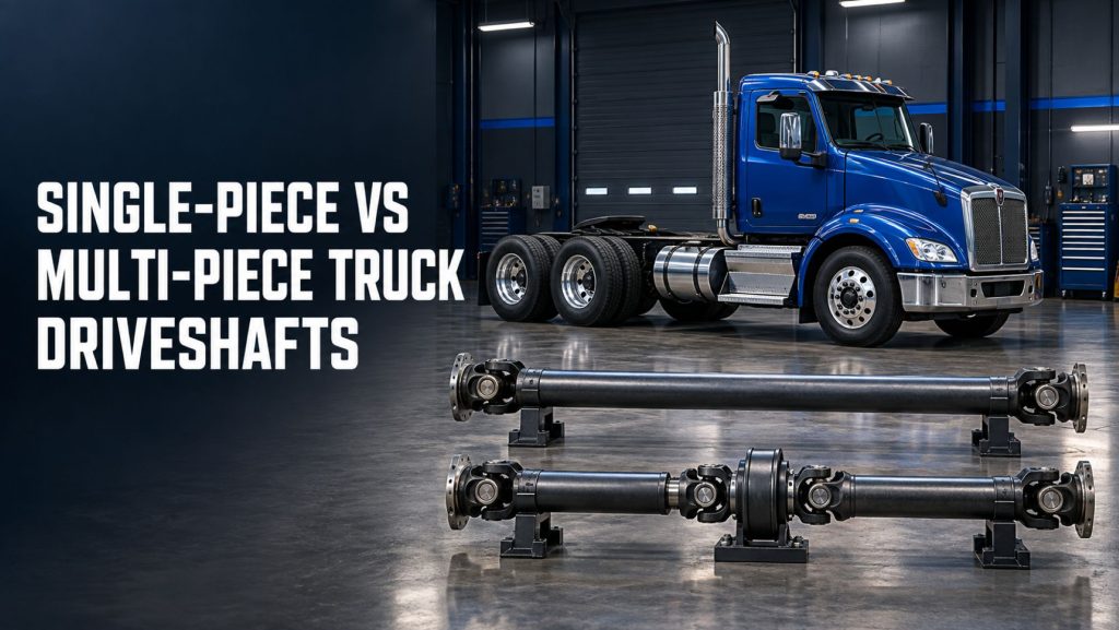
Commercial truck driveshafts transfer rotational power from the transmission to the drive axle or axle group. Although every driveshaft performs the same basic function, the assembly may use one continuous shaft or multiple shaft sections joined through universal joints and supported by one or more carrier bearings.
The choice between a single-piece and multi-piece driveshaft affects operating angles, critical speed, packaging, weight, maintenance, vibration control, and torque capacity. This guide compares both configurations and explains how wheelbase, transmission placement, axle position, suspension movement, and vehicle application influence driveshaft design.
What a Truck Driveshaft Does
The driveshaft is the rotating connection between the transmission output and the drive axle input. Engine torque passes through the commercial truck transmission, into the driveshaft, and then to the axle differential. The differential and axle shafts distribute that torque to the drive wheels.
A driveshaft must transmit torque while accommodating changes in distance and angle caused by frame flex, suspension movement, axle travel, and powertrain position. Universal joints allow the shaft to operate through changing angles, while a slip joint or sliding spline allows its effective length to change as the axle moves. See How Commercial Truck Axles and Differentials Work for the complete power-flow sequence.
What Is a Single-Piece Driveshaft?
A single-piece driveshaft uses one primary tubular shaft between the transmission and the drive axle. A universal joint is normally installed at each end, and a slip section provides the movement needed as the suspension travels.
This arrangement does not require an intermediate support bearing or an additional shaft section. It is most practical when the distance between the transmission and drive axle is short enough for one shaft to operate safely without exceeding its allowable length, angle, torque, or rotational-speed limits.
Single-piece driveshafts are often found on shorter-wheelbase trucks, some medium-duty vehicles, and configurations where the transmission output and axle input can be connected with a reasonably short and properly aligned shaft.
What Is a Multi-Piece Driveshaft?
A multi-piece driveshaft divides the driveline into two or more shaft sections. The forward section connects to the transmission, while the rear section connects to the drive axle. A carrier bearing—also called a center bearing or intermediate support bearing—supports the connection between the sections.
The carrier bearing mounts to a frame crossmember or support structure. It holds the intermediate shaft at the correct height and position while allowing the connected sections to rotate. A rubber cushion around many carrier bearings helps isolate vibration and accommodate limited movement.
Dividing a long driveline into shorter sections improves packaging and helps each section remain below its critical speed. Multi-piece arrangements are common on long-wheelbase straight trucks, extended tractors, buses, vocational trucks, and vehicles with layouts that prevent the use of one practical shaft.
Single-Piece vs Multi-Piece Driveshaft Comparison
| Comparison Area | Single-Piece Driveshaft | Multi-Piece Driveshaft |
|---|---|---|
| Construction | One primary shaft between transmission and axle | Two or more shaft sections with intermediate support |
| Typical layout | Shorter distance between transmission and axle | Long wheelbase or complex chassis packaging |
| Carrier bearing | Normally not required | One or more carrier bearings required |
| Universal joints | Usually fewer | Usually more |
| Parts and weight | Generally lower | Generally higher |
| Maintenance points | Fewer joints and no center support | Additional joints, bearings, brackets, and fasteners |
| Long-chassis suitability | Limited by length, diameter, speed, and angle | Better suited to long or complicated driveline routes |
| Alignment | Correct transmission-to-axle relationship required | Every shaft section and support must be aligned correctly |
| Vibration diagnosis | Fewer components to inspect | More possible sources, including carrier-bearing position and phasing |
Why Driveshaft Length and Critical Speed Matter
A rotating shaft has a natural frequency at which it can begin to bend or whip. The rotational speed associated with this behavior is called critical speed. If a driveshaft operates too close to or above its allowable critical speed, vibration can rise rapidly and the shaft may be damaged.
Critical speed is influenced by shaft length, tube diameter, wall thickness, material, construction, balance, and rotational speed. As a shaft becomes longer, its allowable operating speed generally decreases unless its diameter, material, or design changes. This is one of the main reasons long vehicles often use several shorter shaft sections rather than one extremely long shaft.
Transmission gearing, overdrive ratio, axle ratio, tire size, and road speed all influence driveshaft speed. Their relationship is explained further in Commercial Truck Axle Ratios Explained.
Driveshaft Operating Angles
Universal joints allow a driveshaft to transfer power between components that are not perfectly aligned. A conventional universal joint does not rotate at a perfectly uniform output speed when operating at an angle. A correctly designed driveline uses coordinated joint angles so those speed fluctuations largely cancel each other.
In a single-piece system, the relationship among the transmission output, driveshaft, and axle input must produce acceptable working angles. In a multi-piece system, the angle of every shaft section and joint must be considered, and carrier-bearing position becomes part of the geometry.
Angles that are excessive, unequal, incorrectly phased, or too close to zero can contribute to vibration, joint wear, noise, and driveline damage. Ride-height changes can also alter those angles, which is why some driveline complaints are connected to worn or incorrectly adjusted truck suspension systems.
Universal-Joint Phasing
Phasing describes the rotational relationship between the yokes on a driveshaft. The yokes must be indexed correctly so the universal joints operate in the intended relationship. A shaft assembled out of phase can produce cyclic speed variation and vibration even when the individual joints and tubes appear undamaged.
Phasing is especially important in a multi-piece driveline because several shafts and joints must work together. Splined sections, slip joints, companion flanges, and shaft markings should be assembled according to the component or vehicle manufacturer’s instructions.
Carrier Bearings in Multi-Piece Driveshafts
The carrier bearing supports an intermediate shaft and maintains the designed driveline path. Its mounting bracket must remain secure, and the bearing must rotate smoothly without excessive play. The surrounding rubber support should hold the bearing properly without being torn, collapsed, oil-soaked, or separated.
A failed carrier bearing may create humming, rumbling, vibration, clunking, or visible shaft movement. Replacing the bearing alone may not correct the problem if incorrect angles, imbalance, worn universal joints, damaged brackets, or suspension-height problems caused the failure.
Advantages of a Single-Piece Driveshaft
- Fewer universal joints and connection points
- No carrier bearing or intermediate support bracket
- Lower parts count and potentially lower weight
- Simpler inspection and troubleshooting
- Fewer components that can loosen, wear, or create vibration
Limitations of a Single-Piece Driveshaft
- Practical length is limited by critical speed and tube design
- A longer shaft may require a larger diameter or specialized material
- May not fit around crossmembers, tanks, exhaust components, or mounted equipment
- May be unsuitable when powertrain and axle positions create unacceptable angles
- Long shafts can be harder to handle, balance, transport, and protect from damage
Advantages of a Multi-Piece Driveshaft
- Supports long-wheelbase and extended-frame vehicles
- Uses shorter individual sections with higher critical-speed capability
- Provides flexibility around chassis equipment and crossmembers
- Can establish acceptable working angles across a complicated driveline route
- Allows individual shaft sections to be serviced when appropriate
Limitations of a Multi-Piece Driveshaft
- Additional universal joints, splines, fasteners, and support components
- Carrier bearings introduce another wear and vibration point
- More complex angle measurement and alignment
- Greater sensitivity to incorrect phasing and bearing position
- More inspection and lubrication points on serviceable designs
Common Driveshaft Problems
| Symptom | Possible Causes |
|---|---|
| Speed-related vibration | Shaft imbalance, runout, incorrect angles, damaged tube, missing balance weight, worn joints, or critical-speed problem |
| Clunk during acceleration or deceleration | Worn universal joint, loose flange, spline wear, axle movement, or differential backlash |
| Rumbling or grinding | Carrier-bearing damage, dry universal joint, worn slip section, or related axle problem |
| Squeak at low speed | Dry or failing universal-joint bearing caps |
| Shudder during takeoff | Incorrect angles, suspension wrap, worn mounts, damaged joint, or clutch-related condition |
| Repeated carrier-bearing failure | Misalignment, incorrect mounting height, imbalance, excessive angle, or chassis movement |
| Grease leakage or rust-colored dust | Failed joint seal, loss of lubrication, contamination, or internal bearing wear |
Driveshaft Inspection and Maintenance
Driveshaft inspections should be performed with the truck secured against movement and according to appropriate shop safety procedures. A rotating driveline should never be contacted or inspected from underneath an operating vehicle without an approved diagnostic procedure and suitable equipment.
- Inspect the shaft tube. Look for dents, cracks, corrosion, weld damage, missing balance weights, rubbing marks, or contact damage.
- Check universal joints. Look for looseness, binding, damaged seals, missing hardware, dry bearing caps, grease leakage, or rust-colored powder.
- Inspect slip joints and splines. Check for excessive movement, damaged seals, contamination, wear, and correct lubrication where serviceable.
- Inspect carrier bearings. Check bearing smoothness, rubber support condition, bracket security, mounting position, and surrounding clearance.
- Check flanges and fasteners. Inspect companion flanges, yokes, straps, bolts, and retaining hardware for looseness or damage.
- Review shaft phasing. Confirm that separated or serviced sections were reassembled in the correct indexed relationship.
- Evaluate operating angles. Check transmission, shaft, bearing, and axle positions when vibration or repeated joint failures occur.
- Inspect nearby systems. Engine mounts, transmission mounts, suspension parts, axle seats, torque rods, and ride height can affect driveline alignment.
Lubrication requirements vary. Some universal joints and slip assemblies are serviceable, while others are permanently lubricated. Use the lubricant, interval, and procedure specified by the vehicle or component manufacturer.
Choosing the Correct Driveshaft Configuration
The correct configuration is determined by engineering requirements rather than the assumption that fewer pieces are always better. Important selection factors include:
- Distance between the transmission and drive axle
- Maximum driveshaft rotational speed
- Engine and transmission torque
- Transmission top-gear ratio and axle ratio
- Shaft diameter, wall thickness, material, and critical-speed rating
- Universal-joint series and torque capacity
- Expected suspension travel and operating angles
- Wheelbase, frame layout, tanks, exhaust, and mounted equipment
- Highway, regional, vocational, severe-service, or off-road duty cycle
- Service access, replacement availability, weight, and cost
A driveshaft should not be shortened, lengthened, substituted, or converted without verifying torque capacity, critical speed, balance, joint series, slip travel, angles, clearance, and manufacturer requirements. A shaft that physically fits may still be unsafe at operating speed.
Frequently Asked Questions
Is a single-piece driveshaft stronger than a multi-piece driveshaft?
Not automatically. Strength depends on tube design, material, diameter, wall thickness, joint series, yokes, welds, torque rating, and application. A properly engineered multi-piece system may carry very high torque while meeting length and speed requirements that one shaft could not.
Why do long trucks use carrier bearings?
A carrier bearing supports the connection between shorter driveshaft sections. This makes it possible to span a long chassis while controlling shaft length, critical speed, position, and operating angles.
Can a two-piece driveshaft be replaced with a single-piece shaft?
Only if the replacement is professionally engineered for the vehicle. Length, diameter, critical speed, torque capacity, joint size, clearance, balance, suspension travel, and operating angles must all be verified.
What causes vibration after driveshaft service?
Possible causes include incorrect phasing, reversed or improperly indexed sections, missing balance weights, incorrect carrier-bearing position, damaged joints, flange contamination, excessive runout, loose fasteners, or changed operating angles.
Does suspension ride height affect a driveshaft?
Yes. Ride height changes the axle’s position relative to the transmission and frame. Incorrect height can alter universal-joint angles and slip travel, contributing to vibration or wear. Learn more in How Commercial Truck Suspension Systems Work.
Final Comparison
A single-piece driveshaft offers a simpler layout with fewer joints and support components, making it practical when shaft length, speed, angle, torque, and clearance remain within acceptable limits. A multi-piece driveshaft adds components and maintenance points but makes long wheelbases and complicated chassis layouts possible by dividing the driveline into shorter supported sections.
Neither design is universally superior. Reliability depends on correct engineering, balance, phasing, joint angles, carrier-bearing position, lubrication, mounting, and inspection. The best design is the one properly matched to the truck’s powertrain, wheelbase, suspension, operating speed, and duty cycle.
Continue Exploring Commercial Truck Drivetrain Systems
- How Commercial Truck Transmissions Work
- Commercial Truck Transmission Guides
- How Commercial Truck Axles and Differentials Work
- Axle and Differential Guides
- Commercial Truck Axle Ratios Explained
- Commercial Truck Axles and Differentials
- How Commercial Truck Suspension Systems Work
- Suspension System Guides