
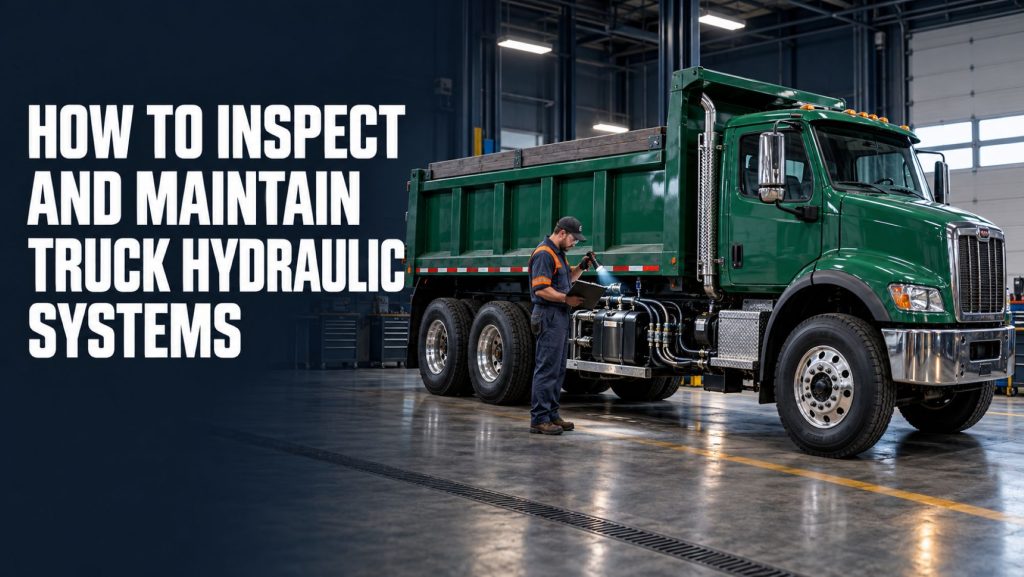
Commercial truck hydraulic systems power dump bodies, trailers, wreckers, cranes, aerial lifts, refuse equipment, snowplows, walking floors, hydraulic motors, utility equipment, and many other vocational components.
These systems can operate under substantial pressure and load. A small leak, restricted hose, contaminated reservoir, damaged fitting, or incorrectly operating pump can reduce equipment performance and develop into a costly or dangerous failure.
Regular inspection and preventive maintenance help identify problems before they cause unexpected downtime, environmental spills, equipment damage, or unsafe movement.
This guide explains how to inspect and maintain commercial truck hydraulic systems, which components require attention, what warning signs to watch for, and when the system should be removed from service for professional diagnosis.
Understand the Complete Hydraulic System
A truck hydraulic system should be inspected as one complete power-transfer system rather than as a collection of unrelated components.
A typical hydraulic power path is:
Engine → Transmission → PTO → Hydraulic Pump → Control Valve → Cylinder or Hydraulic Motor → Reservoir
The major components can include:
- Power take-off
- Hydraulic pump
- Hydraulic reservoir
- Control valves
- Pressure relief valve
- Hydraulic cylinders
- Hydraulic motors
- Suction, pressure, and return hoses
- Fittings and adapters
- Quick-connect couplers
- Filters and strainers
- Reservoir breather
- Hydraulic oil cooler
- Electronic, pneumatic, or mechanical controls
- Pressure, temperature, and position sensors
A problem in one component can affect the operation of the entire system. For example, an obstructed reservoir breather can restrict pump inlet flow, while a blocked return filter can increase backpressure and hydraulic temperature.
Follow the Manufacturer’s Maintenance Requirements
Hydraulic maintenance requirements vary according to the truck, PTO, pump, body equipment, hydraulic fluid, operating temperature, and duty cycle.
Always use the current instructions for the exact components installed on the truck.
Manufacturer information should determine:
- Approved hydraulic fluid
- Normal operating temperature
- Maximum system pressure
- Filter replacement intervals
- Fluid change intervals
- PTO inspection requirements
- Pump operating-speed limits
- Mounting-hardware torque
- Hose and fitting specifications
- Approved testing procedures
A general inspection guide can help identify concerns, but it does not replace model-specific service information.
Hydraulic System Safety
Hydraulic systems can store energy even after the engine and PTO have been shut off.
Pressurized fluid, raised equipment, suspended loads, moving cylinders, rotating shafts, hot surfaces, and shifting truck components can create serious hazards.
Before beginning an inspection or repair:
- Park the truck on a stable surface.
- Apply the parking brake.
- Place the transmission in the required position.
- Lower hydraulic equipment to its supported position whenever possible.
- Shut down the engine when the inspection does not require operation.
- Disengage the PTO.
- Relieve stored hydraulic pressure using the approved procedure.
- Block or mechanically support equipment that could move.
- Use wheel chocks when required.
- Follow the company’s lockout and tagout procedures.
Never work beneath a raised dump body, boom, bed, cab, or other hydraulic equipment unless it is secured with the approved mechanical support.
Never Search for a Hydraulic Leak With Your Hand
A pinhole hydraulic leak can release a narrow stream of fluid at enough pressure to penetrate skin.
High-pressure injection injuries may initially appear minor but can cause severe internal tissue damage.
Use an approved inspection method, such as cardboard or another manufacturer-recommended leak-detection tool, while keeping the body clear of the suspected leak.
Never place a hand, finger, or other body part near a pressurized hose or fitting to feel for a leak.
Anyone who may have suffered a hydraulic-fluid injection injury should receive immediate emergency medical attention and clearly explain that the injury involved pressurized fluid.
Daily or Pre-Operation Inspection
A brief inspection before operating the hydraulic equipment can identify many developing problems.
Check for:
- Fresh hydraulic-fluid leaks
- Low reservoir fluid level
- Damaged or loose reservoir mounts
- Cracked, blistered, crushed, or abraded hoses
- Loose or damaged fittings
- Unsecured hose routing
- Dirty or damaged quick-connect couplers
- Damaged PTO, pump, or valve wiring
- Loose air lines or leaking pneumatic controls
- Unusual pump or PTO noise
- Unexpected vibration
- Slow or uneven equipment movement
- Warning lights or diagnostic messages
Problems discovered during the walk-around should be evaluated before operating the equipment under load.
Inspect the Hydraulic Fluid Level
Check hydraulic fluid with the equipment in the position specified by the manufacturer.
The correct checking position matters because extending or retracting a large hydraulic cylinder can substantially change the amount of fluid in the reservoir.
When checking the level:
- Park the truck on level ground when required.
- Position all cylinders according to the manufacturer’s instructions.
- Clean around the filler cap, dipstick, or sight gauge.
- Confirm that the fluid level is within the approved range.
- Use only the specified hydraulic fluid.
- Avoid overfilling the reservoir.
A low fluid level can allow the pump to draw air. An overfilled reservoir can overflow when cylinders retract and oil returns to the tank.
Inspect Hydraulic Fluid Condition
Hydraulic fluid should be inspected for signs of contamination, overheating, oxidation, or aeration.
Warning signs can include:
- Cloudy or milky appearance
- Foam
- Strong burnt odor
- Unusually dark color
- Visible dirt or metal particles
- Water in the reservoir
- Sludge or varnish deposits
Milky fluid can indicate water contamination or severe aeration. Foam may indicate air entering the system, an incorrect fluid level, a blocked breather, or excessive return-flow agitation.
Fluid appearance alone does not prove that the oil remains suitable for service. High-duty-cycle equipment may benefit from scheduled fluid analysis to measure contamination, viscosity, water content, oxidation, and wear material.
Use the Correct Hydraulic Fluid
Hydraulic fluid performs several jobs:
- Transfers power
- Lubricates pumps and valves
- Carries heat away from components
- Suspends contaminants for filtration
- Protects internal surfaces
- Supports seal performance
The correct viscosity is especially important.
Fluid that is too thick during cold weather can restrict the pump inlet and cause cavitation. Fluid that becomes too thin at high temperature can reduce lubrication and increase internal leakage.
Do not mix hydraulic-fluid types unless compatibility has been confirmed by the equipment and fluid manufacturers.
Inspect the Hydraulic Reservoir
The reservoir should remain securely mounted and protected from damage.
Inspect the reservoir for:
- Cracks
- Corrosion
- Dents
- Leakage around seams or fittings
- Loose mounting straps
- Damaged brackets
- Contact with the frame or nearby components
- Heat exposure from the exhaust system
- Missing or damaged filler caps
- Blocked or contaminated breathers
Steel, aluminum, and polyethylene reservoirs can have different inspection and mounting requirements. Use the procedures appropriate for the installed reservoir.
Maintain the Reservoir Breather
The hydraulic reservoir must breathe as the fluid level rises and falls.
A blocked breather can create pressure or vacuum inside the tank. This can restrict pump inlet flow, contribute to leaks, and interfere with equipment operation.
Inspect the breather for:
- Dirt accumulation
- Oil saturation
- Physical damage
- Water entry
- Loose mounting
- Evidence that the reservoir has been overfilled
Clean or replace the breather according to the manufacturer’s maintenance schedule.
Inspect Hydraulic Hoses
Hydraulic hoses operate under pressure while being exposed to vibration, heat, weather, road debris, chassis movement, and repeated bending.
Inspect the complete visible length of each hose whenever access permits.
Look for:
- Fluid leakage
- Wetness around the hose cover
- Cracks
- Blisters or bubbles
- Exposed wire reinforcement
- Flattened or crushed sections
- Kinks
- Sharp bends
- Twisting
- Heat damage
- Abrasion
- Loose protective sleeves
- Movement against the frame or body
A hose should not be routed where it can rub against frame edges, suspension components, exhaust parts, tires, driveshafts, or moving equipment.
Protective sleeves can reduce abrasion exposure, but they should not be used to hide a damaged hose.
Inspect Hose Ends and Fittings
Pay close attention to hose ends because movement and stress often concentrate near the fitting.
Inspect for:
- Oil around the crimp
- Hose cover pulling away from the fitting
- Corrosion
- Cracked or damaged fittings
- Loose connections
- Misalignment
- Side loading
- Signs that the hose has slipped
Do not repeatedly tighten a leaking fitting without identifying why it is leaking. Excessive tightening can damage threads, seats, O-rings, and component ports.
Fittings should be tightened using the correct procedure and torque specification for the connection type.
Know When a Hydraulic Hose Requires Replacement
A hydraulic hose should be removed from service when damage exceeds the hose or equipment manufacturer’s allowable condition.
Replacement is commonly required when a hose has:
- Active leakage
- Exposed or corroded reinforcement
- Cracks extending through the cover
- Blisters or soft spots
- Severe abrasion
- Crushed or kinked sections
- Damaged fittings
- Heat-damaged covering
- Evidence of fitting movement
- Contamination from incompatible fluid or chemicals
Hydraulic hoses should not be repaired with tape, clamps, sealant, or improvised splices.
A replacement hose must have the correct pressure rating, size, length, temperature rating, fluid compatibility, bend radius, fitting type, and cleanliness level.
Inspect Quick-Connect Couplers
Quick-connect couplers allow a truck wet kit to connect with compatible trailers or equipment.
Inspect couplers for:
- Dirt or debris
- Damaged seals
- Corrosion
- Cracked bodies
- Damaged locking mechanisms
- Leakage
- Incomplete connection
- Missing dust caps
- Pressure and return identification
Clean the connection before attaching the hoses. Contamination introduced through a dirty coupler can circulate through the pump, valves, cylinders, and motors.
Never force a coupler together. Trapped pressure should be relieved using the approved procedure.
Inspect the Hydraulic Pump
The hydraulic pump should operate without excessive leakage, vibration, heat, or unusual noise.
Inspect the pump for:
- Leaks around shaft seals
- Leaks around ports or housing joints
- Loose mounting hardware
- Damaged support brackets
- Excessive vibration
- Whining, rattling, or knocking noises
- Abnormal temperature
- Damaged input shaft or coupling
- Hose weight pulling on the pump ports
A direct-mounted pump may require additional support depending on its weight, length, hose loading, and PTO manufacturer requirements.
A change in pump noise should be investigated promptly. It can indicate cavitation, aeration, internal wear, bearing damage, excessive speed, or incorrect fluid viscosity.
Recognize Pump Cavitation
Cavitation occurs when the pump cannot receive hydraulic fluid under suitable inlet conditions.
Vapor bubbles can form and collapse inside the pump, damaging internal surfaces.
Possible warning signs include:
- High-pitched whining
- Rattling or gravel-like noise
- Reduced hydraulic flow
- Erratic equipment movement
- Excessive heat
- Pump damage or rapid wear
Possible causes include:
- Low reservoir fluid level
- Undersized suction hose
- Collapsed or restricted inlet hose
- Blocked inlet strainer
- Cold or overly viscous fluid
- Excessive pump speed
- Blocked reservoir breather
- Incorrect pump mounting location
Recognize Hydraulic Aeration
Aeration occurs when air enters and becomes mixed with the hydraulic fluid.
Possible symptoms include:
- Foamy fluid
- Erratic or spongy equipment movement
- Pump noise
- Reduced system performance
- Fluid overflow
- Excessive heat
Possible causes include loose suction fittings, cracked inlet hoses, low fluid level, poor return-line placement, excessive fluid agitation, or an incorrect reservoir configuration.
Inspect the Power Take-Off
The PTO transfers mechanical power from the transmission or engine to the hydraulic pump.
Inspect the PTO for:
- Oil leakage
- Loose mounting hardware
- Unusual gear noise
- Incomplete engagement
- Unexpected disengagement
- Damaged shift cables or linkage
- Leaking air lines
- Damaged wiring or connectors
- Faulty engagement indicators
- Excessive output-shaft movement
Grinding during engagement can indicate an incorrect operating procedure, excessive gear speed, a clutch problem, damaged PTO components, or improper adjustment.
PTO lubricant may be supplied by the transmission or through another approved lubrication arrangement. Confirm the requirements for the exact PTO and transmission.
Inspect Remote Pump Drives
Some hydraulic pumps are connected to the PTO through a remote driveshaft or coupling.
Inspect remote drives for:
- Loose fasteners
- Damaged universal joints
- Incorrect operating angles
- Missing lubrication
- Shaft damage
- Vibration
- Damaged support bearings
- Missing or damaged guards
Rotating shafts and couplings must remain properly guarded. Never inspect or service an exposed rotating driveline while it is operating.
Inspect Hydraulic Control Valves
Control valves direct hydraulic fluid to cylinders, motors, and other equipment.
Inspect valves for:
- External leakage
- Loose mounting
- Damaged spools or controls
- Sticking or delayed movement
- Damaged air lines or electrical connectors
- Unintended cylinder movement
- Excessive heat
- Incorrect neutral operation
A valve that does not return to neutral or allows equipment to move unexpectedly should be removed from service and diagnosed.
Inspect the Pressure Relief Valve
The pressure relief valve limits maximum hydraulic-system pressure.
Possible signs of a relief-valve problem include:
- Equipment unable to lift the rated load
- Excessive heat
- Continuous hydraulic noise
- Pressure above the approved limit
- Slow equipment operation
- Frequent operation at the relief setting
Relief pressure should be tested with calibrated equipment using the approved procedure.
Do not increase the relief setting simply to make weak or overloaded equipment operate. Excessive pressure can damage hoses, pumps, valves, cylinders, trailer equipment, and structural components.
Inspect Hydraulic Cylinders
Hydraulic cylinders convert fluid pressure into linear force.
Inspect each cylinder for:
- Rod damage
- Corrosion or pitting
- Bent rods
- Leaking rod seals
- Leaking ports or fittings
- Damaged barrel surfaces
- Loose or worn mounting pins
- Cracked mounts
- Damaged retaining hardware
- Uneven or jerky movement
- Internal leakage or drifting
A damaged rod surface can quickly destroy the rod seal and introduce contamination into the cylinder.
Cylinder mounts, pins, bushings, and surrounding structure should be inspected along with the hydraulic component.
Inspect Hydraulic Motors
Hydraulic motors power walking floors, live-bottom conveyors, winches, mixers, blowers, and other rotating equipment.
Inspect hydraulic motors for:
- External leakage
- Loose mounting hardware
- Abnormal noise
- Excessive temperature
- Reduced speed or torque
- Damaged shaft seals
- Loose couplings
- Restricted case-drain lines where used
A blocked or incorrectly connected case-drain line can damage seals and increase internal pressure in systems that require one.
Inspect Hydraulic Filters
Filters protect hydraulic components by removing contamination from the fluid.
A hydraulic system may use:
- Return-line filters
- Pressure-line filters
- Case-drain filters
- Inlet strainers where approved
- Reservoir filler screens
- Breather filters
Inspect filter housings for leaks, damage, and loose mounting. Check restriction indicators when installed.
A blocked filter can open its bypass valve, allowing unfiltered oil to circulate. It can also create excessive backpressure or restrict pump inlet flow, depending on its location.
Replace filters at the required interval and whenever contamination or component failure makes additional service necessary.
Inspect the Hydraulic Oil Cooler
Continuous-duty and high-heat hydraulic systems may use an oil cooler.
Inspect the cooler for:
- Blocked fins
- Dirt and debris
- Fluid leaks
- Damaged hoses
- Loose mounts
- Fan damage
- Electrical faults
- Restricted airflow
Clean the cooler using a method that will not bend the fins or force contamination deeper into the core.
A cooler should not be used to hide excessive heat caused by an incorrectly designed or malfunctioning hydraulic system.
Monitor Hydraulic Temperature
Excessive heat shortens hydraulic-fluid life and can damage seals, hoses, pumps, valves, and other components.
Possible causes of overheating include:
- Operating continuously against the relief valve
- Incorrect valve position
- Excessive pump speed
- Restricted hoses or couplers
- Blocked filters
- Insufficient reservoir capacity
- Internal pump leakage
- Incorrect hydraulic fluid
- High return-line backpressure
- Insufficient cooling
- Using an intermittent-duty system continuously
Use the manufacturer’s temperature limits rather than relying on whether a component merely feels hot.
Inspect Electrical and Pneumatic Controls
Modern hydraulic systems often combine mechanical, electrical, pneumatic, and electronic controls.
Inspect:
- Wiring harnesses
- Connectors
- Ground connections
- Fuses and relays
- Control switches
- Solenoids
- Air lines and fittings
- PTO engagement indicators
- Remote controls
- Pressure and temperature sensors
- Safety interlocks
Damaged wiring, low air pressure, leaking lines, failed sensors, or incorrect programming can prevent PTO engagement or cause the hydraulic system to operate incorrectly.
Safety interlocks should be tested using the approved procedure and should never be bypassed.
Perform a Controlled Operational Check
When conditions allow and the manufacturer’s procedure is available, perform a controlled operational check after the visual inspection.
Observe:
- PTO engagement
- Pump sound
- Equipment speed
- Smoothness of movement
- Ability to hold position
- Pressure response
- Return-to-neutral operation
- Fluid temperature
- Leaks under pressure
- Warning lights or fault codes
Keep personnel clear of the equipment’s movement area during the test.
Stop operation immediately if the system produces severe noise, uncontrolled movement, a major leak, smoke, extreme heat, or another unsafe condition.
Check Hydraulic System Performance
A hydraulic system can appear functional while operating below its designed performance.
Performance checks may include:
- System pressure
- Pump flow
- Equipment cycle time
- PTO speed
- Engine speed
- Hydraulic temperature
- Filter restriction
- Cylinder drift
- Return-line backpressure
- Pump inlet vacuum
Use calibrated test equipment and approved test points. Pressure gauges, flow meters, temperature instruments, and diagnostic software must be rated for the system being tested.
Control Hydraulic Contamination
Contamination control is one of the most important parts of hydraulic-system maintenance.
Contaminants can enter through:
- Dirty filler openings
- Uncapped hoses
- Dirty quick-connect couplers
- Damaged breathers
- Improper fluid-transfer equipment
- Replacement components
- Worn seals
- Internal component failure
- Water condensation
- Road and worksite exposure
Good contamination-control practices include:
- Cleaning around filler openings before service
- Using clean, sealed fluid containers
- Using dedicated fluid-transfer equipment
- Capping open hoses and ports immediately
- Cleaning quick-connect couplers before connection
- Pre-cleaning replacement components when required
- Replacing contaminated filters
- Flushing the system after certain component failures
- Using fluid analysis for severe-duty equipment
Service the System After a Component Failure
A failed pump, motor, valve, or cylinder can release metal particles, seal material, and other debris into the hydraulic system.
Replacing only the failed component may allow remaining contamination to damage the new part.
Depending on the failure, service may require:
- Draining contaminated fluid
- Cleaning the reservoir
- Flushing hoses and lines
- Replacing filters
- Inspecting valves and cylinders
- Cleaning or replacing the oil cooler
- Sampling the replacement fluid
- Performing an early follow-up filter change
The component manufacturer’s contamination-cleanup procedure should determine the required work.
Bleed Air Using the Approved Procedure
Air can enter the system after hose, pump, cylinder, reservoir, or valve service.
Some hydraulic systems are designed to purge air through controlled cycling, while others require a specific bleeding procedure.
Do not loosen a pressurized fitting in an attempt to bleed the system.
Cycle the equipment only according to the manufacturer’s instructions, with personnel clear of moving components and the reservoir maintained at the correct fluid level.
Check Mounting Hardware and Brackets
Hydraulic components are exposed to truck vibration, road shock, chassis flex, and equipment movement.
Inspect the mounting of:
- Reservoirs
- Pumps
- PTOs
- Control valves
- Filters
- Oil coolers
- Cylinders
- Hydraulic motors
- Hose clamps
- Remote shaft bearings
Look for loose fasteners, elongated mounting holes, cracked welds, distorted brackets, missing isolators, and contact between components.
Tighten mounting hardware using the correct specifications and procedures.
Common Hydraulic System Warning Signs
| Warning sign | Possible causes |
|---|---|
| Slow equipment movement | Low pump speed, worn pump, restricted filter, low fluid, internal leakage, or undersized components |
| Jerky or uneven movement | Air in the system, low fluid, binding equipment, contaminated valve, or cylinder problem |
| Pump whining or rattling | Cavitation, aeration, excessive speed, low fluid, or restricted inlet |
| Excessive heat | Relief-valve operation, restricted flow, worn pump, incorrect valve position, or insufficient cooling |
| Foamy fluid | Air entering the system, incorrect fluid level, poor return flow, or blocked breather |
| Cloudy or milky fluid | Water contamination or aeration |
| Equipment drifts | Internal cylinder leakage, valve leakage, or load-holding valve problem |
| PTO disengages | Control fault, air-pressure problem, adjustment issue, overload, or internal damage |
| Repeated hose failures | Incorrect hose, poor routing, excessive pressure, hydraulic shock, heat, or movement |
| Fluid around pump shaft | Worn seal, shaft movement, excessive case pressure, or misalignment |
Common Hydraulic Maintenance Mistakes
Avoid maintenance practices that can create additional system problems.
- Searching for leaks with a hand
- Working beneath unsupported hydraulic equipment
- Opening a pressurized connection
- Mixing unapproved hydraulic fluids
- Using dirty funnels or transfer containers
- Leaving hoses and ports uncapped
- Replacing a hose with an incorrect pressure rating
- Reusing damaged fittings
- Overtightening leaking connections
- Increasing relief pressure to compensate for weak performance
- Replacing a failed pump without cleaning the contaminated system
- Ignoring filter restriction indicators
- Continuing to operate an overheating system
- Bypassing safety interlocks
- Using sealant or tape as an external hose repair
Suggested Inspection Schedule
The following is a general planning framework. Actual intervals must follow the truck and component manufacturers’ requirements.
| Inspection period | Typical areas of attention |
|---|---|
| Before operation | Fluid level, visible leaks, hoses, couplers, mounts, controls, and warning indicators |
| During operation | Noise, vibration, temperature, equipment speed, smooth movement, and leakage under pressure |
| After operation | New leaks, overheated components, damaged hoses, loose mounts, and abnormal fluid loss |
| Scheduled preventive maintenance | Filters, fluid condition, breathers, mounting torque, PTO, pump, valves, cylinders, motors, and controls |
| After component failure | System contamination, reservoir cleaning, flushing, filters, oil cooler, and related-component inspection |
| Seasonal or severe-duty service | Fluid viscosity, cold-weather operation, cooler condition, corrosion, water contamination, and shortened service intervals |
Keep Hydraulic Maintenance Records
Maintenance records can reveal recurring problems that may not be obvious during a single inspection.
Useful records include:
- Fluid type and quantity
- Fluid and filter change dates
- Fluid-analysis results
- Hose replacement dates
- Pump and PTO repairs
- Pressure and flow test results
- Operating-temperature readings
- Recurring leak locations
- Diagnostic fault codes
- Equipment cycle times
- Component serial numbers
A pattern of repeated hose, pump, seal, or filter failures can indicate a system-design, contamination, pressure, temperature, or operating problem rather than unrelated component defects.
When to Remove the Hydraulic System From Service
The equipment should be removed from service when continued operation could cause injury, equipment damage, or environmental contamination.
Examples include:
- A pressurized hydraulic leak
- A hose with exposed reinforcement or severe damage
- An unsupported or drifting raised body
- Uncontrolled equipment movement
- A cracked cylinder mount
- A damaged reservoir mount
- Major pump or PTO noise
- Extreme hydraulic temperature
- Repeated relief-valve operation
- A failed safety interlock
- Contaminated fluid after a component failure
- A missing rotating-shaft guard
The system should remain out of service until the cause has been identified and the required repair has been completed.
When Professional Hydraulic Service Is Needed
Some inspections can be completed during a normal truck walk-around, but diagnosis and repair may require trained hydraulic technicians and specialized equipment.
Professional service may be needed for:
- Pressure and flow testing
- Relief-valve adjustment
- Pump efficiency testing
- Internal valve diagnosis
- Cylinder rebuilding
- Hydraulic motor repair
- PTO repair or adjustment
- Electronic control diagnosis
- System flushing after failure
- Oil-cooler contamination
- Recurring overheating
- Repeated hose or seal failures
Using qualified service providers is especially important when the work involves stored pressure, suspended equipment, electronic interlocks, or critical load-holding components.
Commercial Truck Hydraulic Inspection Checklist
A general hydraulic-system inspection can follow this sequence:
- Secure the truck and lower or mechanically support the equipment.
- Disengage the PTO and relieve stored pressure.
- Inspect the ground and chassis for fluid leakage.
- Check reservoir level and fluid condition.
- Inspect the reservoir, mounts, filler, and breather.
- Inspect suction, pressure, return, and case-drain hoses.
- Inspect fittings, adapters, and quick-connect couplers.
- Inspect the PTO, pump, mounts, and support brackets.
- Inspect control valves and relief-valve components.
- Inspect cylinders, motors, pins, and mounting structures.
- Inspect filters, restriction indicators, and the oil cooler.
- Inspect electrical wiring, air lines, switches, and interlocks.
- Perform an approved controlled operational check.
- Record defects, test results, maintenance, and repairs.
This checklist provides a starting point. It should be expanded using the inspection requirements for the exact truck and equipment.
Continue Learning About PTO and Hydraulic Systems
Regular inspection and contamination control are essential to reliable hydraulic-system operation.
Continue with the other Truck Equipment Atlas PTO and Hydraulic System Guides:
- How Commercial Truck PTO and Hydraulic Systems Work
- Commercial Truck Power Take-Off Types Explained
- How to Choose a PTO and Hydraulic Pump
- Commercial Truck Wet Kits Explained
Visit the PTO & Hydraulic System Guides page to explore the complete educational guide library.
Manufacturer Technical References
Use current model-specific inspection, safety, maintenance, and repair information for every component installed on the truck.
- Muncie Power Products Power Take-Offs
- Muncie Power Products Hydraulic Pumps
- Muncie Power Products Hydraulic Hoses and Fittings
- Parker Chelsea Power Take-Off Products
- Parker Hose Products Division
Final Thoughts
Commercial truck hydraulic systems perform demanding work by transferring power through pressurized fluid.
The reliability of the complete system depends on clean hydraulic fluid, unrestricted pump inlet flow, properly routed hoses, secure fittings, effective filtration, correct pressure settings, adequate cooling, and sound mechanical and electronic controls.
Daily inspections can identify leaks, damaged hoses, low fluid, loose mounts, contaminated couplers, and abnormal noise before the equipment is placed under load. Scheduled maintenance can address filters, fluid condition, breathers, mounting hardware, PTO components, pumps, valves, cylinders, motors, and coolers.
Maintenance should never place a technician beneath unsupported equipment or in contact with pressurized fluid. Stored pressure must be relieved, moving equipment must be secured, and suspected leaks must be checked with an approved method rather than a hand.
A consistent inspection program, accurate maintenance records, and prompt attention to changing equipment behavior can reduce downtime, extend component life, and help keep truck hydraulic systems operating safely and efficiently.
Truck Equipment Atlas will continue expanding its PTO, wet-kit, hydraulic-system, and vocational-truck resources as the equipment library grows.