
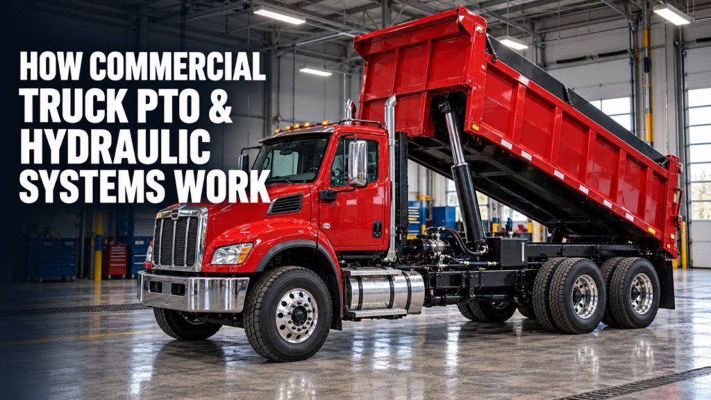
Commercial trucks often need power for equipment that has nothing to do with moving the vehicle down the road. Dump bodies must be raised, tow trucks must operate winches, refuse trucks must compact material, utility trucks must position aerial devices, and tank trucks may need to run pumps or blowers.
A power take-off, commonly called a PTO, allows the truck’s engine and drivetrain to power this auxiliary equipment. In many applications, the PTO drives a hydraulic pump that converts mechanical rotation into hydraulic flow. That flow moves through hoses, valves, cylinders, motors, filters, and a reservoir to perform useful work.
The PTO and hydraulic system must be engineered as a complete package. PTO speed, available torque, pump displacement, hydraulic pressure, flow rate, reservoir capacity, hose size, valve design, cooling, and the equipment’s operating cycle all affect system performance.
This guide explains how commercial truck PTO and hydraulic systems work, how power moves from the engine to the equipment, what the major components do, and why proper system matching is critical.
What Is a Commercial Truck PTO?
A power take-off is a mechanical device that transfers power from the truck’s engine or transmission to auxiliary equipment. Rather than sending all available engine power through the driveline to move the wheels, the PTO provides an additional output that can operate equipment mounted on the truck or trailer.
Many traditional PTOs attach to an opening on the transmission. Gears inside the PTO engage with a transmission gear and rotate an output shaft. That shaft may connect directly to a hydraulic pump or drive a remotely mounted component through a driveline.
Depending on the truck and application, PTO-driven equipment may include:
- Hydraulic pumps
- Dump bodies and hoists
- Tow-truck winches and wheel lifts
- Refuse bodies and compactors
- Cranes and material-handling equipment
- Aerial lifts and utility equipment
- Vacuum pumps
- Liquid-transfer pumps
- Dry-bulk blowers and compressors
- Concrete mixers
- Snowplows and spreaders
- Roll-off and hook-lift systems
The PTO and Hydraulic Power Path
A typical transmission-driven hydraulic system can be simplified into the following sequence:
Engine → Transmission → PTO → Hydraulic Pump → Control Valve → Cylinder or Motor → Reservoir
Each part performs a different function:
- The engine produces mechanical power.
- The transmission provides the gear that drives the PTO.
- The PTO transfers rotational power out of the transmission.
- The hydraulic pump creates fluid flow.
- The control valve directs that flow.
- The cylinder or motor converts hydraulic energy into movement.
- The reservoir stores returning hydraulic fluid so it can be reused.
The actual system may also include filters, relief valves, check valves, flow controls, coolers, accumulators, electronic controls, sensors, and additional hydraulic circuits.
How the PTO Receives Power
In a transmission-mounted PTO, a gear inside the PTO meshes with a compatible transmission gear. When the PTO is engaged and the transmission conditions allow rotation, the PTO gear turns the output shaft.
The relationship between transmission speed and PTO output speed is determined by the PTO ratio. A PTO may turn slower than, approximately equal to, or faster than the driving gear, depending on its design.
PTO selection must account for more than whether the unit physically fits the transmission opening. Important compatibility factors include:
- Transmission make and exact model
- PTO opening location and bolt pattern
- Driving-gear design and rotation
- PTO speed ratio
- Required horsepower and torque
- Intermittent or continuous-duty operation
- Output-shaft and pump-mounting arrangement
- Space around the transmission, frame, exhaust, and suspension
- Control and interlock requirements
A PTO that bolts to the transmission but has the wrong ratio, rotation, capacity, or gear design is not a correct installation.
Common Commercial Truck PTO Locations
Transmission-Mounted PTO
Transmission-mounted PTOs are among the most common designs on vocational trucks. They attach to a PTO opening on the transmission and use an internal transmission gear as their power source.
The PTO may be installed on the side, bottom, or another approved location depending on the transmission. The available location affects clearance, lubrication, pump position, and driveline routing.
Engine-Driven PTO or Front-Engine Drive
Some equipment receives power directly from the engine or an engine-mounted drive. This arrangement can provide power independently of the transmission’s selected gear, but it must be engineered around the engine, accessory drive, cooling system, and chassis layout.
Transfer-Case PTO
Certain vocational, off-highway, and specialty vehicles use a transfer-case PTO. This arrangement may be appropriate when the vehicle’s driveline configuration includes a transfer case with an approved auxiliary-power opening.
Electric PTO
An electric PTO, often called an ePTO, uses an electric motor to operate a hydraulic pump or other auxiliary equipment. It may receive energy from a high-voltage traction battery, a dedicated battery system, or another electrical power source.
An ePTO can allow equipment operation without continuously running a diesel engine. However, the motor, inverter, battery capacity, charging strategy, hydraulic load, thermal management, and operating duration must all be matched to the application.
PTO Engagement Types
PTOs can use different engagement methods depending on the transmission, vehicle, and application.
Shift-Type PTO
A shift-type PTO mechanically moves a gear or clutching component into engagement. Some designs require the transmission and PTO gears to be stopped before engagement. The exact engagement procedure must come from the PTO, transmission, and vehicle manufacturers.
Hot-Shift PTO
A hot-shift PTO uses a clutch pack or another controlled mechanism that can permit engagement under approved operating conditions without requiring every internal component to be completely stationary.
Hot-shift does not mean the PTO can be engaged at any engine speed, road speed, load, or transmission condition. Electronic limits and manufacturer procedures still apply.
Constant-Drive PTO
A constant-drive arrangement keeps part of the PTO system rotating whenever its driving component turns. A clutch or hydraulic control may determine when power is delivered to the equipment.
Stationary and Mobile PTO Operation
Some PTO systems operate only while the truck is parked. Others are designed for mobile or live-drive operation while the vehicle is moving.
Stationary Operation
Stationary PTO operation is common on dump trucks, cranes, service trucks, and other equipment that performs work while parked. Interlocks may require the parking brake to be applied, the transmission to be in an approved range, or the vehicle speed to be zero.
Mobile Operation
Mobile PTO operation is used when the equipment must function while the truck moves. Examples can include refuse collection, street sweeping, snow removal, concrete mixing, and certain spreading or pumping applications.
Mobile operation requires careful coordination among vehicle speed, transmission range, engine speed, hydraulic flow, cooling capacity, and safety controls.
What the Hydraulic Pump Does
The hydraulic pump receives rotational power from the PTO and creates fluid flow. The pump does not simply create pressure by itself. Pressure develops when the flow encounters resistance from a load or restriction.
For example, a pump may move fluid toward a dump-body cylinder. As the cylinder begins lifting the loaded body, resistance increases and system pressure rises. When the load stops moving or reaches the end of its travel, pressure can rise rapidly until a relief valve opens or the control system changes state.
Common mobile hydraulic pump types include:
- Gear pumps
- Vane pumps
- Fixed-displacement piston pumps
- Variable-displacement piston pumps
- Multiple-section or tandem pumps
Each design has different characteristics involving pressure capability, efficiency, noise, flow control, contamination sensitivity, cost, and application suitability.
Direct-Mount and Remote-Mount Pumps
Direct-Mount Pump
A direct-mount hydraulic pump attaches directly to the PTO output. This arrangement can reduce the number of driveline components and create a compact installation.
Direct mounting still requires attention to pump weight, support, shaft compatibility, rotation, clearance, lubrication, hose routing, and manufacturer limits. A heavy or unusually long pump may require additional support.
Remote-Mount Pump
A remote-mounted pump is installed away from the PTO and connected through a driveshaft or other approved mechanical connection. This may solve clearance or weight-distribution problems, but it adds alignment, guarding, driveline-angle, support-bearing, and maintenance requirements.
Hydraulic Flow and Pressure
Flow and pressure describe different parts of hydraulic-system performance.
- Flow is the amount of fluid moving through the system over time, commonly expressed in gallons per minute.
- Pressure is the force per unit area created when the flowing fluid encounters resistance, commonly expressed in pounds per square inch.
Flow largely influences how quickly a cylinder extends or a hydraulic motor turns. Pressure determines how much force or torque the system can produce against a load.
Increasing flow does not automatically increase the system’s lifting force. Increasing pressure does not automatically make the equipment move faster. Both must be matched to the actuator, valve, hoses, reservoir, and equipment requirements.
Pump Displacement and PTO Speed
Pump displacement describes the amount of fluid a pump moves during each revolution. Pump speed and displacement work together to determine theoretical flow.
A larger-displacement pump moves more fluid per revolution than a smaller pump. A faster pump speed also increases flow, but every pump has operating-speed limits.
PTO ratio, engine speed, transmission design, and pump displacement must therefore be considered together. An incorrectly matched PTO ratio can cause:
- Insufficient hydraulic flow
- Equipment that moves too slowly
- Excessive pump speed
- Excessive heat generation
- Cavitation or aeration
- Reduced pump life
- Engine overspeed or excessive engine loading
Understanding Hydraulic Horsepower
Hydraulic power depends on both pressure and flow. A commonly used theoretical relationship is:
Hydraulic horsepower = Pressure in PSI × Flow in GPM ÷ 1,714
For example, a system operating at 2,000 PSI and 20 gallons per minute produces approximately 23.3 theoretical hydraulic horsepower.
The engine and PTO must supply more than the theoretical hydraulic horsepower because pumps, hoses, valves, driveline components, and actuators are not perfectly efficient. The exact system must be sized using manufacturer data and realistic operating conditions.
Major Hydraulic System Components
Hydraulic Reservoir
The reservoir stores hydraulic fluid and gives returning oil time to release heat, air, moisture, and some suspended contamination. It also provides a consistent fluid supply to the pump.
Reservoir capacity and design depend on system flow, operating cycle, available space, cooling requirements, and application. A tank that is too small can contribute to high fluid temperatures, aeration, and poor system performance.
Suction Line
The suction line carries fluid from the reservoir to the pump. It must be correctly sized and routed to minimize restriction. A restricted, collapsed, leaking, or undersized suction line can cause cavitation, noise, reduced flow, and pump damage.
Pressure Line
The pressure line carries fluid from the pump toward the control valve and working equipment. Hoses, tubing, and fittings must be rated for the system’s maximum pressure, temperature, fluid, routing, and operating environment.
Return Line
The return line carries fluid from the valve or actuator back to the reservoir. Excessive return-line restriction creates backpressure and heat and can interfere with equipment operation.
Control Valve
The control valve determines where hydraulic fluid flows. Depending on the valve position, it may extend or retract a cylinder, rotate a motor, hold a load, or return fluid to the reservoir.
Valves may be operated manually, pneumatically, hydraulically, electrically, or through an electronic control network.
Pressure-Relief Valve
A pressure-relief valve helps protect the hydraulic system from excessive pressure by opening a path for fluid when pressure reaches its set point.
The relief valve is a protective device, not a normal method of controlling equipment speed. Continuous operation across the relief valve converts power into heat and can damage the pump, fluid, seals, and other components.
Hydraulic Cylinder
A hydraulic cylinder converts fluid pressure and flow into linear movement. Cylinders are used to raise dump bodies, move booms, extend outriggers, tilt equipment, and operate many other truck-mounted systems.
Cylinder force depends on hydraulic pressure and the effective piston area. Retracting force may differ from extending force because the rod reduces the effective area on one side of the piston.
Hydraulic Motor
A hydraulic motor converts hydraulic flow and pressure into rotational movement. Motors may operate winches, conveyors, augers, fans, mixers, reels, and other rotating equipment.
Filters and Strainers
Filters remove contamination from hydraulic fluid. Depending on the system, filtration may be installed in the pressure line, return line, reservoir, or another approved location.
Incorrect filter selection can create excessive restriction or fail to provide the required contamination control. Filter rating, flow capacity, pressure capability, bypass design, and service indicator must match the system.
Hydraulic Cooler
A hydraulic cooler removes heat from the fluid. Coolers are especially important in continuous-duty systems, high-flow applications, compact installations, and equipment that spends long periods operating under load.
Open-Center Hydraulic Systems
In a basic open-center system, the pump continuously moves fluid while it is operating. When the control valve is in neutral, the open center allows fluid to circulate back toward the reservoir at relatively low pressure.
Moving the valve blocks or redirects the open path and sends flow to an actuator. Pressure rises as the actuator encounters the load.
Open-center systems are common in many straightforward mobile hydraulic applications, particularly when using a fixed-displacement pump.
Closed-Center and Load-Sensing Systems
Closed-center systems operate differently. When the control valves are in neutral, the system does not provide the same unrestricted return path used by a basic open-center circuit.
Many closed-center mobile systems use a variable-displacement pump that adjusts its output according to system demand. Load-sensing controls can signal the pump to provide the flow and pressure needed by the active function.
These systems can support complex equipment with multiple hydraulic functions, but pump, valve, control, and plumbing compatibility is essential.
How a Basic Dump-Truck Hydraulic Cycle Works
A simplified dump-body operating cycle illustrates how the PTO and hydraulic components work together:
- The truck is positioned and secured according to the body manufacturer’s operating procedure.
- The operator places the transmission and vehicle controls in the required condition.
- The operator engages the PTO.
- The PTO begins rotating the hydraulic pump.
- The pump draws fluid from the reservoir.
- The control valve directs pressurized flow to the hoist cylinder.
- The cylinder extends and raises the dump body.
- The control is returned to neutral when the required position is reached.
- When lowering is commanded, the valve allows fluid to return from the cylinder toward the reservoir.
- The body lowers according to the system design and operating controls.
- The PTO is disengaged according to the approved procedure when hydraulic power is no longer required.
This is a general explanation, not an operating procedure for a specific truck. Dump-body controls, tailgates, interlocks, stabilizers, transmission settings, and safety procedures vary by equipment design.
What Is a Commercial Truck Wet Kit?
A wet kit is a collection of hydraulic components installed on a truck to operate hydraulic trailer or body equipment. The exact package varies by application.
A typical wet kit may include:
- Power take-off
- Hydraulic pump
- Reservoir
- Control valve
- Hydraulic hoses and fittings
- Filters or strainers
- In-cab controls
- Trailer hydraulic connections
- Mounting brackets and protective equipment
A single-line dump-trailer wet kit, two-line system, walking-floor system, liquid-transfer system, and multi-function lowboy system can have very different flow, pressure, reservoir, valve, and cooling requirements.
Electronic PTO Controls and Interlocks
Modern vocational trucks often integrate PTO operation with the engine, transmission, body controller, and vehicle electronics.
Depending on the vehicle, the control system may monitor:
- Parking-brake status
- Transmission range
- Clutch position
- Vehicle speed
- Engine speed
- PTO engagement confirmation
- Hydraulic pressure or temperature
- Body position
- Outrigger or stabilizer position
- Operator-presence or safety switches
The engine control system may also manage engine speed during PTO operation. Rather than relying only on the accelerator pedal, a programmed operating mode can maintain a specified engine speed or respond to hydraulic load.
Hydraulic Heat and Efficiency
No hydraulic system is perfectly efficient. Friction, internal leakage, pressure drops, fluid restriction, and mechanical losses convert part of the input power into heat.
Excessive heat can be caused by:
- Continuous operation across the pressure-relief valve
- Undersized hoses or fittings
- Restricted filters
- An undersized reservoir
- Excessive pump speed
- Internal pump, valve, cylinder, or motor leakage
- Incorrect hydraulic fluid
- Contaminated or aerated fluid
- Insufficient cooler capacity or airflow
- Operating beyond the designed duty cycle
High fluid temperature can reduce viscosity, damage seals, accelerate oxidation, reduce lubrication, and shorten component life.
Cavitation and Aeration
Cavitation and aeration are different conditions, but both can create noise, erratic operation, and component damage.
Cavitation
Cavitation can occur when the pump cannot receive enough fluid at its inlet. Vapor cavities form and then collapse as they move into higher-pressure areas of the pump.
Possible causes include a restricted suction line, cold or overly viscous fluid, excessive pump speed, an obstructed reservoir breather, low fluid level, or poor reservoir design.
Aeration
Aeration occurs when outside air enters the hydraulic fluid. Possible entry points include loose suction fittings, damaged hoses, incorrect return-line placement, low reservoir level, or failed seals.
Aerated fluid may appear foamy and can cause erratic movement, noise, heat, and poor lubrication.
Common PTO and Hydraulic System Problems
| Symptom | Possible Areas to Investigate |
|---|---|
| PTO will not engage | Controls, wiring, air supply, solenoid, clutch switch, interlock, transmission condition, or internal PTO damage |
| PTO grinds during engagement | Incorrect engagement procedure, gears still rotating, clutch drag, wrong adjustment, or gear damage |
| Hydraulic equipment operates slowly | Low pump speed, worn pump, low fluid, restriction, internal leakage, incorrect valve position, or excessive load |
| System lacks lifting force | Low pressure, incorrect relief setting, worn pump, cylinder leakage, valve leakage, or load beyond system capacity |
| Hydraulic system overheats | Relief-valve operation, restriction, internal leakage, undersized tank, incorrect fluid, excessive duty cycle, or insufficient cooling |
| Pump makes unusual noise | Cavitation, aeration, low fluid level, damaged pump, misalignment, or excessive speed |
| Equipment moves erratically | Air in the system, contamination, sticking valve, damaged cylinder, control problem, or inconsistent pump flow |
| Hydraulic fluid leaks | Damaged hose, loose fitting, failed seal, cracked component, excessive pressure, abrasion, or poor routing |
| PTO or pump runs excessively hot | Overload, misalignment, incorrect lubrication, excessive speed, bearing damage, or restricted hydraulic flow |
These symptoms are diagnostic starting points. The exact cause should be determined through approved testing rather than replacing components based only on the symptom.
Why PTO and Hydraulic System Matching Matters
A hydraulic pump should not be selected independently from the PTO, and a PTO should not be selected independently from the transmission and equipment.
A complete application review should consider:
- Required hydraulic pressure
- Required flow rate
- Equipment operating speed
- Pump displacement and speed range
- PTO speed ratio and rotation
- PTO torque and horsepower capacity
- Engine speed and available engine power
- Transmission and PTO-opening compatibility
- Stationary or mobile operation
- Intermittent or continuous duty
- Reservoir capacity
- Filtration and contamination-control requirements
- Cooling requirements
- Available chassis space and component clearance
- Control and safety-interlock requirements
Oversizing one component does not correct an undersized or incompatible system. A larger pump may exceed the PTO capacity, overspeed the equipment, overwhelm the reservoir, or require more engine power than the truck can provide at the intended operating speed.
PTO and Hydraulic System Safety
PTO and hydraulic systems can create crushing, injection, entanglement, falling-load, and high-temperature hazards. Equipment should be operated and serviced only according to the vehicle, PTO, hydraulic-component, and body-equipment manufacturers’ procedures.
- Never work beneath raised equipment unless it is secured with the approved mechanical supports.
- Never use a hand to search for a pressurized hydraulic leak.
- Keep hands, clothing, tools, and loose objects away from rotating shafts.
- Do not operate equipment with missing driveline guards.
- Relieve stored hydraulic pressure before disconnecting components.
- Allow hot fluid and components to cool before service.
- Use properly rated hoses, fittings, gauges, and replacement components.
- Follow lockout, blocking, parking-brake, and vehicle-securing procedures.
- Do not bypass safety interlocks to force PTO operation.
High-pressure fluid can penetrate skin and cause a serious medical emergency even when the injury initially appears small.
PTO and Hydraulic System Maintenance
Maintenance intervals vary by component, fluid, application, operating hours, environment, and manufacturer. Common inspection areas include:
- PTO lubricant supply and signs of leakage
- PTO mounting fasteners and transmission attachment
- Engagement controls, wiring, air lines, and indicator lights
- Output shaft, pump mount, and support brackets
- Remote drivelines, universal joints, guards, and alignment
- Hydraulic fluid level and condition
- Reservoir mounting, cap, breather, and internal contamination
- Filters and service indicators
- Hoses for leaks, abrasion, cracks, kinks, and heat damage
- Fittings, clamps, and protective sleeves
- Cylinders, rods, pins, bushings, and seals
- Valves, solenoids, controls, and relief settings
- Hydraulic motors, pumps, and coolers
- System temperature, operating noise, and function speed
Changes in operating speed, sound, heat, pressure, or control response should be investigated before a minor condition develops into a larger failure.
Frequently Asked Questions
Does a PTO create additional engine power?
No. A PTO transfers available engine power to auxiliary equipment. Power used by the PTO is no longer available for another purpose, and mechanical and hydraulic losses reduce the power that ultimately reaches the equipment.
Does a hydraulic pump create pressure or flow?
A hydraulic pump creates flow. Pressure develops when that flow encounters resistance from the load, valves, hoses, actuators, or other parts of the circuit.
Can any PTO fit any transmission?
No. The PTO must match the exact transmission, opening, driving gear, rotation, ratio, torque capacity, controls, and installation requirements.
Can a larger hydraulic pump make equipment work faster?
A larger-displacement pump may increase flow, but it can also exceed PTO capacity, pump-speed limits, valve capacity, hose capacity, reservoir capacity, cooling ability, or the equipment’s safe operating speed. The complete system must be evaluated before changing pump size.
Why does hydraulic fluid become hot?
Hydraulic systems create heat through friction, pressure losses, internal leakage, restrictions, and operation across relief valves. Excessive heat can also indicate incorrect component sizing, contaminated fluid, insufficient cooling, or operation beyond the intended duty cycle.
Can a PTO operate while the truck is moving?
Only when the complete vehicle, transmission, PTO, hydraulic system, and equipment are designed and approved for mobile operation. Many systems are intended only for stationary use.
What is the difference between a PTO and a wet kit?
The PTO transfers mechanical power from the truck. A wet kit is the broader hydraulic package, which may include the PTO, pump, reservoir, valves, hoses, controls, filters, and connections needed to operate equipment.
Continue Learning About PTO and Hydraulic Systems
This guide provides the foundation for understanding how commercial truck PTO and hydraulic systems operate. Continue with the other Truck Equipment Atlas PTO and Hydraulic System Guides as they are published:
- Commercial Truck Power Take-Off Types Explained
- How to Choose a PTO and Hydraulic Pump
- Commercial Truck Wet Kits Explained
- How to Inspect and Maintain Truck Hydraulic Systems
Visit the PTO & Hydraulic System Guides library to explore the complete educational guide collection.
Related Equipment Systems
- Commercial Truck Transmissions
- Electrical Systems
- Brake Systems
- Suspension Systems
- Axles & Differentials
Manufacturer Technical References
Use current model-specific instructions and application approvals when selecting, installing, operating, or maintaining PTO and hydraulic equipment. These manufacturer resources provide additional technical context:
- Parker Chelsea PTO and mobile power resources
- Muncie Power Products PTO and hydraulic resources
- Eaton mobile power products and technical information
Final Thoughts
A commercial truck PTO converts the engine and transmission’s mechanical power into an auxiliary output. In many vocational applications, that output drives a hydraulic pump, which creates the fluid flow used to operate cylinders, motors, hoists, winches, cranes, compactors, blowers, and other equipment.
Successful operation depends on matching the complete system. PTO ratio and capacity must work with the transmission, engine speed, pump displacement, hydraulic pressure, required flow, reservoir, valves, hoses, cooling system, controls, and equipment duty cycle.
Understanding this complete power path makes it easier to compare PTO types, select hydraulic components, diagnose performance problems, plan maintenance, and specify a truck that can operate its vocational equipment safely and effectively.
Truck Equipment Atlas will continue expanding its PTO, wet-kit, hydraulic-component, and vocational-equipment resources as the library grows.